11
Description Block Commands
This chapter documents the Description Block Commands for Dracula in alphabetical order.
ABORT-MULT-STAMP
ABORT-MULT-STAMP = YES/NO
Description
Ends checking when a multi-stamped situation occurs. This command is useful when running large jobs that take a long time to complete. When ABORT-MULT-STAMP = YES, the relative STAMP module terminates, and the output error cells are still generated in the output GDS file for you to debug. The files that draculaInteractive needs will be kept so that you can debug the error layers in the draculaInteractive environment, if you have already set KEEPDATA = YES or KEEPDATA = DRACULAINTERACTIVE.
The Dracula tool creates a new file called MULSTAMP.DAT,which is an ASCII file reporting the multi-stamped locations. This file contains the "UPPER" and "LOWER" trapezoids with the location and the node number. This file is automatically generated when there is a
multi-stamp or a soft connection violation.
KEEPDATA = DRACULAINTERACTIVE works only in Dracula 4.8 and IC 445 version and higher versions. The command KEEPDATA = INQUERY will only work in Dracula versions that are lower than Dracula 4.8 and the IC 445 version.Arguments
Terminates checking when a multi-stamped violation occurs
Example
ABORT-MULT-STAMP = YES
The following is the format for MULSTAMP.DAT:
/*------------------------------------------------*/
LOWER-LAYER: MET1
trapzoid: (10, 10), (20, 10), (10, 20), (20, 20)
UPPER-LAYER: POLY
trapzoid: (15, 7), (18, 7), (15, 12), (18, 12) NODE: 2
trapzoid: (14, 17), (17, 17), (14, 25), (17, 25) NODE: 3
/*------------------------------------------------*/
LOWER-LAYER: MET1
trapzoid: (30, 30), (40, 30), (30, 40), (40, 40)
UPPER-LAYER: POLY
trapzoid: (25, 32), (32, 32), (25, 35), (32, 35) NODE: 4
trapzoid: (35, 27), (37, 27), (35, 33), (37, 33) NODE: 5
ABORT-P-G-SHORT
ABORT-P-G-SHORT = YES/NO/ALL/SHORT/OPEN
Description
Specifies whether to abort a job if a power or ground node shorts or opens. If the text you specify as power or ground shorts or opens, the job aborts at the POSATT module. No PRINTFILE.SUM is generated. You must check your log file for information on the short or open. Power text can be VCC, VDD, or *:P. Ground text can be VSS, GND, GROUND, or *:G.
To find the power or ground short or open, you must remove the ABORT-P-G-SHORT command and add the MULTILAB and SAMELAB commands in the Operation block.
Arguments
Aborts a job if a power or ground node is open or a power is shorted with a ground.
Aborts a job if a power or ground node is open or shorted with any other signal.
Aborts a job if a power or ground node is shorted with any other signal.
Aborts a job if a power or ground node is open.
Examples
ABORT-P-G-SHORT = YES
ABORT-P-G-SHORT = SHORT
ABORT-SOFTCHK
ABORT-SOFTCHK = YES/NO
Description
Aborts checking when a soft connection violation occurs. This command is useful when running large jobs that take a long time to complete. When ABORT-SOFTCHK = YES, an abort alerts you to a major SOFTCHK problem prior to spending CPU time running the complete job.
To examine a SOFTCHK problem, do one of the following:
- Run another job, which runs only the SOFTCHK commands, through completion.
- Re-run the same job with ABORT-SOFTCHK = NO. Take your existing rule file and eliminate all commands not needed for the SOFTCHK rules. Be sure to change ABORT-SOFTCHK = YES to ABORT-SOFTCHK = NO. Then run this second job from beginning to end.
Arguments
Aborts checking when a soft connection violation occurs.
Example
ABORT-SOFTCHK = YES
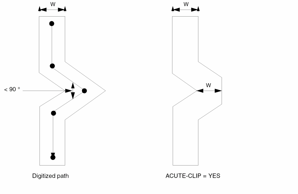
ACUTE-CLIP
ACUTE-CLIP = YES/NO
Description
Modifies path geometries that form an acute angle. This command clips the outside corner of the geometry to the width of the path.
Arguments
Example
ACUTE-CLIP = YES
ALLOW-RECONNECT
ALLOW-RECONNECT = YES/NO
Description
Use this command to turn-on incremental connection which allows reconnection up to 16 times. SOFTCHK must be placed right after the connect group when you use this command. See the Example 3 in the “SCONNECT” command section of chapter 13.
Arguments
ANGLED-EDGE-TOL
ANGLED-EDGE-TOL [=] {<value> | YES/ON | NO/OFF}
Description
This command enables and defines, or disables a tolerance setting for the DRC checking operation on non-manhattan edges.
See “ANGLED-EDGE-TOL” for a complete description of this command.
ARRAY
ARRAY = location array-name
Description
Flags cells that form an array. This command checks the array and truncates it to its minimal configuration. You can specify special array- handling options to conserve resources. Use ARRAY only for GDSII (maximum of 80).
Arguments
Expands the cell into an array and specifies the portion to check.
Cell name from which to make the array. Expansion dimensions are in the input file.
Examples
ARRAY = BOUNDARY A
The array is a 10 x 10 expansion of cell A.
ARRAY = CORNER B
The array is a 10x10 expansion of cell B.
ARRAY-ENABLED
ARRAY-ENABLED = YES/NO
When ARRAY-ENABLED=YES, Dracula searches your layout to find regular array structures. When array structures are found, only the outer ring of array structures is checked against foreign cells. This command should be used to memory designs and ASIC designs with embedded memory.
If you are in an intermediate verification stage and need quick results, you can use ARRAY-ENABLED. Because Dracula does not process the entire array structures, ARRAY-ENABLED reduces the amount of data processed.
Checking Method
Arguments
Examples
ARRAY-ENABLED = YES
AUTOMATCH
AUTOMATCH = YES/NO/SMART
Description
Directs LVS to use an alternate method that does not require text assigned to the initial correspondence points. LVS usually requires text assigned to the initial correspondence points. AUTOMATCH can find these points when they are not assigned text.
LVS automatically switches to the AUTOMATCH algorithm when it cannot locate initial correspondence points. This automatic switch occurs even if you did not use the AUTOMATCH command in your run file. AUTOMATCH is useful when you check LVS in composite mode.
You can use the AUTOMATCH command even if you placed text on the layout to identify initial correspondence points. Text is essential to match groups of corresponding signals whose interconnections are not identifiable to LVS. For example, an array of data bus signals can have similar interconnection characteristics. LVS can identify these similar signals only when you place unique text on the layout. Also, when LVS reduces transistors to gates or parallel/series structures, LVS requires text on the layout to identify power and ground nodes and ambiguous signals.
Arguments
Directs LVS to use an alternate algorithm to locate initial corresponding points.
When LVS cannot locate initial correspondence points, SMART turns on the AUTOMATCH function. Default.
Example
AUTOMATCH = YES
BLACKBOX-FILE
BLACKBOX-FILE = filename
Description
Specifies the black box text file name. The black box file defines Hcells to be masked by black boxes. Each line in the file must list the following items:
- The text name
-
The x and y coordinates
Dracula centers the pin geometry at these coordinates. The coordinates are relative to Hcell coordinates. The x and y are not case sensitive. Optionally, you can use width (w) and height (h) specifications to define the shape of the pin. The default for both is two database units. The w and h are not case sensitive. The black box file accepts a tab as a delimiter. -
The attached layer
If you do not specify ATTACH, Dracula attaches the text according to the CONNECT-LAYER reference. - The name of the Hcell
There are three ways to apply black box-like features in Dracula composite mode checking:
- To make the BLACKBOX-FILE command more powerful, modify the database so that black box Hcells are empty. You do this by referencing the Hcell to a dummy empty cell so only small squares around points defined by the BLACKBOX-FILE command exist after Dracula runs the EXPAND module. Because Dracula processes no other geometry, this improves performance.
- When you specify the FRAME BY option for an Hcell in composite mode checking, all geometries inside the cell (except those falling in the ring of the cell) are deleted. The ring size is defined as the FRAME BY value. If you specify the GEN-TEXT-FRAME command, all Hcells are considered FRAME BY Hcells, and the ring size is defined as the GEN-TEXT-FRAME value. You must make sure all texts needed for connections are on the frame of the Hcells. For this feature, the BLACKBOX-FILE command is not mandatory.
- For some designs, you might want to keep the geometries from only some of the connecting layers for some of the Hcells (black box). You can append the stopping connecting layer name to an Hcell so that only the geometries on or above this connecting layer are read. For this feature, the BLACKBOX-FILE command is not mandatory.
For more information about using black boxes, refer to
Checking Method
Example 1
BLACKBOX-FILE abc.htx
IN    x=41   y=90  ATTACH=poly   inv   w=0.6  h=1
OUT   x=89   y=44  ATTACH=metal  inv
VDD   x=123  y=96  ATTACH=met    nand  w=10
Example 2
The following is an example for specifying stopping layers:
*DESCRIPTION
.
.
HCELL-FILE = blackbox.tab
.
.
*END
*INPUT-LAYER
.
.
CONNECT-LAY = PWELL MET1 MET2
.
.
*END
INV1    INV   MET2
NAND1   NAND  MET1
NA2     NA2
For INV1, only MET2 geometries are read. For NAND1, both MET1 and MET2 geometries are read because MET2 is specified before MET1. For NA2, data of all the input layers is read.
Example 3
HCELL-FILE = cell.tab
INV     INV1    MET1
NAND    NAND    MET2
XYZ     XYZ      FRAME BY 2.0    MET2
DDD     DDD
ABC     ABC     MET
If Hcells have layers appended, only the geometries of the specified layer and layers above are read in.
*INPUT-LAYER.
;
PWELL=1
DIFPN=2
POLY =3        ;CTEXT=28 ATTACH=POLY
CONT=5
MET=6     ;CTEXT=29 ATTACH=MET
VAPOX=7      ;TEXT=30
PISL=4
SUBSTRATE= BULK 59
;
MET2=10
VIA=11
;
CELLBNDY = 54        ;BOUNDRY LAYER FOR RECTILINEAR CELLBOXX
;
CONNECT-LAY= NSUB PWELL PSRCDRN NSRCDRN POLY MET MET2
*END
The Hcells read in geometries according to the following table:
| Cell | Layer |
|---|---|
BLOCK-NAME-ONLY
BLOCK-NAME-ONLY = YES/NO
Description
When verifying an Edge database, you can use the layout block name as a cell name for LVS checking. In most circumstances, the rep name is “layout” and the revision name is “current.” For example, the command BLOCK-NAME-ONLY = YES assumes all cell names have the suffix “/layout/current” and chooses only the block name as the cell name to verify.
Arguments
Selects only the block name when encountering a cell name.
Example
BLOCK-NAME-ONLY = YES
BOUNDING-BOX
BOUNDING-BOX = cell-name layer-name
Description
Specifies the bounding box of a cell as an identification layer for special checks. Used for hierarchical and composite modes only.
Arguments
Name of the layer used for the bounding box of the cell. You can use this trapezoid layer in the Operation block for layer operations.
Example
*DESCRIPTION
 .
 .
 BOUNDING-BOX = MATX, MATRICE
 .
 .
 *END
 .
 *INPUT-LAYER
 .
 ACTIVE = 2
 .
 *END
 *OPERATION
 .
 AND ACTIVE MATRICE ACTMAT
 NOT ACTIVE MATRICE ACT
 EXT ACTMAT LT 0.8 DRC1 50
 EXT ACT    LT 1.0 DRC2 51
.
.
*END
BOXMAP
BOXMAP = layout_box_element_name1/schematic_subckt_name1 ,layout_box_element_name2/schematic_subckt_name2
...
,layout_box_element_nameN/schematic_subckt_nameN
Description
Specifies the corresponding layout box element the way that a schematic box element should be compared to in an LVS comparison. The command overwrites the *.EQUIV specification in the schematic netlist if there’s a conflict.
Arguments
The user-defined device name in the element box command.
The schematic .SUBCKT name for a schematic box element.
Example
*.EQUIV IN1=spiral_rad
.SUBCKT spiral_rad T1 T2
.ENDS
.SUBCKT spiral_turn T1 T2
.ENDS
.SUBCKT TEST1 P1 P2 P3 P4
X2 P1 P2 spiral_rad nr=4.5 rad=6e-05 w=1.5e-05 s=1.5e-06
X3 P3 P4 spiral_turn nr=3.5 rad=5e-05 w=1.5e-05 s=1.5e-06
.ENDS
*DESCRIPTION
 .
 .
*DESCRIPTION
.....
PARSET INDP ID IN IW IS LL
BOXMAP = IN2/spiral_rad, IN3/spiral_turn
....
*END
...
*OPERATION
...
ELEMENT IN2 ME5I1 ME4 ME5A
ELEMENT IN3 ME5I2 ME4A ME5B
...
LEXTRACT INDP ME5I2 BY IN2 INDPAR1
EQUATION LL = ID+IN+IW+IS
LEXTRACT INDP ME5I2 BY IN3 INDPAR2&
EQUATION LL = ID+IN+IW+IS
.....
In the above example, the BOXMAP command specifies that instances of the schematic box element spiral_rad should be compared with instances of the layout box element IN2 (overwrites the *.EQUIV specification). Instances of the schematic box element spiral_turn should be compared with instances of the layout box element IN3.
BOX-M-COMPARE
BOX-M-COMPARE = YES/NO
Description
Use with BOX-M-FACTOR=YES to smash parallel box, but not take m-factor into account while comparing.
Arguments
All parallel boxes will be smashed and m-factor will be taken into account while LVS comparison. This is the default.
Parallel boxes will be smashed but the comparison will not carry about m-factor.
Examples
BOX-M-FACTOR = YES
BOX-M-COMPARE = NO
BOX-M-FACTOR
BOX-M-FACTOR = YES/NO
Description
Allow Dracula to smash parallel boxes.
Arguments
All parallel boxes of the same type will be smashed. If the box instance has a parameter named "M" this parameter is used as the M-factor for this box instance. If there is no “M” parameter, the M-factor is 1. See “BOX-M-IGNORE” and BOX-M-COMPARE.
Parallel boxes will not be smashed. This is the default.
Examples
BOX-M-FACTOR = YES
BOX-M-IGNORE
BOX-M-IGNORE = boxtype_1 boxtype_2 boxtype_3 ....
Description
Use with BOX-M-FACTOR = YES to specify boxes that will not be smashed.
Arguments
Specify the type of boxes to exclude from the smashing operation.
Examples
BOX-M-FACTOR = YES
BOX-M-IGNORE = IND1 VART
CAP-POLARITY
CAP-POLARITY =subtype1,subtype2, ...
Description
The ’P’ option of LVSCHK/LPECHK commands checks the ELEMENT capacitor’s polarity regardless of the subtype, which is all right when there is only one type of capacitor. However, with more than one kind of capacitors, Dracula has problems controlling over what types of capacitors should have polarity check.
In the 4.81 and subsequent versions, this new command, CAP-POLARITY lets the ’P’ option of the LVSCHK and LPECHK commands to only have impact on the specified subtypes of capacitors. That is,
- If the CAP-POLARITY command is not used and if the P option is turned on , the polarity of every capacitor will be checked regardless of its subtype.
- If CAP-POLARITY command is used, only the capacitors of the subtypes specified in this command will be checked.
Arguments
One or two-character CAP subtypes
Example
CAP-POLARITY = A, B
This example specifies that only capacitors of subtypes A and B should have a polarity check.
CARE-SPLIT-ORDER
CARE-SPLIT-ORDER = YES/NO
Description
Checks the input order of split gates and merges them into one series structure. If the input order is not the same, this command does not merge the gates. Use this command for LVS or HLVS jobs.
You must also specify the S option in LVSCHK or LPECHK. If you use the command without the S option, a warning message appears. Refer to the
Arguments
Merges the gates into one series structure only when the input order of the gates is the same.
Example
CARE-SPLIT-ORDER = YES
CELLBOX-LAYER
CELLBOX-LAYER = l-num
Description
Creates cell boundaries, referred to as cell boxes, for each Hcell. Dracula places these cell boxes into a cell named 0CELLBOX under a layer number specified by the l-num parameter. The coordinates of cell boxes are relative to 0,0 of the composite plane. This cell also contains textual Hcell information.
Checking Method
Arguments
Specifies the layer name for the cell box. For GDSII format, l-num has a range of 0 to 63.
The format of this cell (GDSII) is the same as the original database unless you specify otherwise with a SYSOUT command. Therefore, you can display the Hcell boxes from your original graphics system.
Note that Dracula creates another file named CELLBOXX.DAT, which Dracula uses internally and is accessible by using Dracula Interactive.
Example
CELLBOX-LAYER = 59
CELL-CHILD-TEXT
CELL-CHILD-TEXT = NO/YES
Description
Specifies whether to place layout text originating from layout cells contained in Hcell child cells in the Hcell plane. By default, Dracula places only text originating in the Hcells.
Checking Method
Arguments
Uses only text originating in the Hcells. Default.
Places child cell text in the Hcell plane. Expands text originating in Hcell child cells into the Hcell if it is global to all placements of the individual child cells, such as for VDD and GND. If nonglobal text exists in Hcell child cells, the YES option results in numerous unrelated pins shorting together.
Example
CELL-CHILD-TEXT = YES
CELL-ERROR-REP
CELL-ERROR-REP = ONCE/HIER/ALL/ORIG-ALL/ORIG-DRC/cell-name
Description
Specifies the format of cell-based error segments generated by hierarchical and flat mode HDRC checks. Hcell errors are errors in cells and cell environments that are common to all placements of a given cell. For details about checking for these errors, refer to Chapter 3, “Checking Design Rules (DRC).”
CELL-ERR-REP only functions for DRC jobs. Dracula ignores CELL-ERR-REP if any ERC, LVS, or LPE commands are present in the rule file
Arguments
Causes the cell error-flag outputs for an Hcell to be instantiated in the OUTPUT error cell at a location corresponding to the first placement of the Hcell in the database starting from the lower left corner. Dracula places the error segments relative to the composite plane within the error cell. Dracula displays Hcell errors only once regardless of how many times you place a particular Hcell. Use in hierarchical mode only. Default.
Causes the cell error-flag outputs for an Hcell to be instantiated in the OUTPUT error cell at all locations where the Hcell is instantiated in the original database. Dracula reports the error output in a two-level hierarchy. Dracula places Hcell errors in an Hcell error cell and invokes instantiations from the error cell. Hcell errors not common to all the Hcells are stored in the OUTPUT error cell. Use in hierarchical mode only.
Same as HIER mode except Dracula flattens error-flagged cell instances to the top level and outputs them to error cells. Nothing is output to the Hcell error cell. This form of output is similar to flat Dracula.
Reports error cells and output cells generated by the layer operations (for example, SIZE and SELECT operations) in the original design hierarchy. Use in hierarchical or flat mode.
Outputs error cells to the original hierarchy. Use in hierarchical or flat mode.
Reports error flags from the cell name you specify in that cell only. The cell name you specify in the rules file must be the same as the reported Dracula cell name. Use only in hierarchical or flat mode. You can specify multiple cells.
 *DESCRIPTION
  ...
  CELL-ERROR-REP = DERR05
  CELL-ERROR-REP = DERR10
  ...
 *END

    *OPERATION
     ...
  AND POLY DIFF GATE OUTPUT DERR 5
  ...
  EXT POLY LT 6 OUTPUT DERR 10
  ...
 *END
Examples
This example instantiates the error flag outputs in the OUTPUT error cell.
CELL-ERROR-REP = ONCE
This example places the error flag outputs hierarchically.
CELL-ERROR-REP = HIER
This example displays error flag outputs as in flat Dracula.
CELL-ERROR-REP = ALL
This example displays error flag outputs in original cell.
CELL-ERROR-REP = ORIG-DRC
This example reports error data in cell DERR05.
CELL-ERROR-REP = DERR05
CELL-LIBRARY
CELL-LIBRARY = YES/NO
Description
Saves a copy of the original database when you size a layout design. This is helpful when changing the technology of a layout.
When you specify CELL-LIBRARY with a SIZE operation, Dracula stores the original database, which preserves the original hierarchy of the cell being sized. Use CELL-LIBRARY with the SIZE operation only. Specify the CELL-LIBRARY command in a hierarchical Dracula rules file.
Arguments
Stores a copy of the original database.
CHECK-MODE
CHECK-MODE = FLAT/CELL/HIER/COMP/MULTI
Description
Specifies the mode in which hierarchical Dracula operates. Place this command at the beginning of the rules file. The default is flat mode, which allows all flat Dracula files to run unchanged.
Checking Method
Flat, cell, hierarchical, composite, or multilevel.
Arguments
Flattens the layout database as in flat Dracula. Default.
You can specify the output layer (trapezoid format) and the OUTPUT c-name the same as when you run flat Dracula.
Establishes cell mode. Running cell mode is equivalent to running a flat check on each of the cells. Dracula reports discrepancies and errors for each Hcell.
In cell mode HDRC, Dracula automatically selects Hcells according to internal criteria. With all other cell mode checks (HERC, HLVS, and HLPE), you must select the Hcells.
When running cell mode HDRC, send the output from each HDRC check to different layer numbers (l-num) to distinguish them in the Hcell error cell.
You can specify the output layer (trapezoid) and the OUTPUT c-name in cell mode. The output layer data is kept separately within each cell.
A reserved layer boundary (boundary.cel) is always generated in cell mode and contains trapezoidal Hcell box boundaries for each Hcell. Dracula can use these for trimming (AND operation) oversized data that extends outside the boundary of the Hcell.
Generates a complete HDRC check of the layout. Dracula chooses Hcells and runs HDRC checks in each Hcell, in the composite, and in the interface from Hcell to Hcell and Hcell to composite plane.
When running hierarchical mode HDRC, send the output from each HDRC check to different layer numbers (l-num) to distinguish them in the Hcell error cell.
To speed up the HDRC hierarchical process, specify a maximum environment value as follows;
CHECK-MODE = HIER FASTuser-defined-max-env-value
When you specify this value, PDRACULA creates a data file named ENVLAY.DAT. This file keeps the correct environment values for each LOGICAL operation. You can also specify the variable setenv FHDRC in your operation environment to speed up HDRC.
If you specify both the setenv FHDRC variable and a maximum environment value in the Description block, the second method has the highest priority. The maximum environment value you specify can be smaller that some of the environment values in ENVLAY.DAT. PDRACULA compares the values in ENVLAY.DAT with the maximum values you define and generates the correct environment value for later use.
When the specified environment value is as follows:
CHECK-MODE = HIER OPTIMIZE
it will automatically switch from hierarchical mode to flat mode if necessary, and set ENVIRONMENT-MAX to 2.0 microns. It will not skip the violated rules, but still generate the input cards for them and let SPACING do the required optimization.
Dracula automatically switches from hierarchical mode to flat mode if it does not find an Hcell.
Runs checks on the composite plane, the composite-to-Hcell pins, and the Hcell-to-Hcell pins. For HLVS, you must specify the Hcells for both the schematic subcircuits and layout cell names using the HCELL-FILE command. HLVS composite CHECK-MODE checks for overlapping information and reports it in the .lvs file.
Run cell mode before composite mode to be sure Hcells are clean and verified. In some cases, where Hcells are empty and only the pins are provided, you might want to run a composite mode HLVS check without a cell mode check.
In hierarchical and composite modes, if the input layer has not already been flattened, you can specify only the output layer (trapezoid format with two levels of hierarchy). If polygon output is required, the output layer generated by the SIZE command can be flattened and sized by zero with the OUTPUT command. To do the SIZE operation hierarchically, you must specify the EXCEPTION-ON=[HSP-OUTPUT] command. This results in a two-level output with CELL-ERROR-REP=HIER.
Generates a complete HDRC check of the layout in multilevel mode. Dracula chooses Hcells suitable for multilevel hierarchy and creates directories for checking each Hcell and a directory for running flat checks.
During a multilevel HDRC, Dracula checks the selected Hcells in the order they occur in the design hierarchy, from bottom to top. Dracula replaces each checked Hcell with an abstract of the Hcell, where it is placed in an Hcell at the next level of the design hierarchy. Dracula automatically runs large dimension DRC checks and checks with nodal options in the flat directory. The output from each run is kept in its run directory.
When you run multilevel HDRC, Hcells can contain other Hcells. Dracula automatically replaces child Hcells with an abstract of the Hcell. Dracula generates the abstracts using the FRAME BY command.
To determine the frames for the framed Hcells
INNERBOX.CEL is the protected area reduced by 2 * maximum oversize value + maximum environment size (maximum DRC rule).
For more information about using different run modes, see “About Run Modes” in the “Selecting a Run Mode” chapter in the Dracula User Guide.
Examples
CHECK-MODE = FLAT   (default)

CHECK-MODE = CELL

CHECK-MODE = HIER

CHECK-MODE = COMP

CHECK-MODE = MULTI
CHECK-PATH
CHECK-PATH = CENTER-LINE/YES/NO
Description
Checks polygons that were created by expanding paths in the EXPAND module.
Arguments
The EXPAND module checks path center-lines for acute or non-45 degree angles.
The EXPAND module checks polygons expanded from paths.
The EXPAND module does not check polygons expanded from paths.
Default.
Example
*DESCRIPTION
CHECK-PATH = CENTER-LINE
.
.
*END
CMOS-NTYPE
CMOS-NTYPE =subtypeN1,subtypeN2, ...
Description
The LVSCHK or LPECHK commands in the Operation Block of commands will form inverters with N/P MOS pair. However, the inverter will not be formed if the names of the MOS subtypes are not one-character long; that is, if the MOS is not N/P pair.
In Dracula 4.81 and subsequent versions, this CMOS-NTYPE command in the description block of the rule file lets you form inverters with 2-character subtypes.
Arguments
Example
CMOS-NTYPE = NC, NN, NE
In this example, it will form inverters if the subtype of NMOS is NC, NN, or NE.
CMOS-PTYPE
CMOS-PTYPE =subtypeN1,subtypeN2, ...
Description
The LVSCHK/LPECHK commands in the Operation Block of commands will form inverters with N/P MOS pair. However, the inverter will not be formed if the names of the MOS subtypes are not one-character long; that is, if the MOS is not N/P pair.
In Dracula 4.81 and subsequent versions, this CMOS-PTYPE command in the description block of the rule file lets you form inverters with 2-character subtypes.
Arguments
Example
CMOS-PTYPE = PC, PP, PE
In this example, it will form inverters if the subtype of PMOS is PC, PP or PE.
CNAMES-CHK-OFF
CNAMES-CHK-OFF = YES/NO
Description
Overrides default CNAMES-CSEN=NO for GDSII input system
Arguments
Overrides default CNAMES-CSEN=NO
Example
CNAMES-CHK-OFF = YES
CNAMES-CSEN
CNAMES-CSEN = YES/NO
Description
Specifies cell name and text name case sensitivity for all commands that contain cell or text names. These include, but are not limited to PRIMARY, DELCEL, ARRAY, OUTLIB, POWER-NODE, GROUND-NODE, PULL-UP, PULL-DOWN, PROBE, SELECT LABEL, LCONNECT, ECONNECT, and HCELL.
This command affects all cell and text names you specify in the layout and in EDTEXT or HEDTEXT files.
To specify only text name case sensitivity, and not cell name, you must specify the TNAMES-CSEN command.
Arguments
Passes the exact name and character cases from the commands and text files to the jxrun.com file. Default when you define the SYSTEM command as CADENCE, or OPUS.
Converts all cell and text names to uppercase.
If CNAMES-CSEN = YES and TNAMES-CSEN = NO, Dracula passes the exact name and character cases from the commands to the jxrun.com file and converts the text names to uppercase.
If CNAMES-CSEN = YES and TNAMES-CSEN = YES, Dracula passes the exact name and character cases from the commands and text file to the jxrun.com file.
If CNAMES-CSEN = NO and TNAMES-CSEN = YES, Dracula converts the cell names to uppercase and passes the exact text names to the jxrun.com file.
If CNAMES-CSEN = NO and TNAMES-CSEN = NO, Dracula converts all cell and text names to uppercase.
Example
CNAMES-CSEN = YES
POWER-NODE= VDD
GROUND-NODE = VSS
OUTLIB = drcout
CONN-ALL-WIRE
CONN-ALL-WIRE = YES/NO
Description
Forces node connections among all cell texts with the same text name. In composite mode, this command implies CONN-INTER-WIRE and forces all cell texts with the same name to be connected without looking at the wire numbers, if any.
Checking Method
Arguments
Example
CONN-ALL-WIRE = YES
CONN-INTER-WIRE
CONN-INTER-WIRE = YES/NO
Description
Forces node connections among internally wired cell text, even though they are not physically connected. Usually, Dracula checks the node connections among those internally wired cell texts with the same virtual number and reports the warnings only if the nodes are not physically connected. The CONN-INTER-WIRE command suppresses the connection check and forces the connection.
CONN-INTER-WIRE has the same effect on composite nodes connected to internally virtual wired cell pins as the FRAME BY command. The CONN-INTER-WIRE = YES command covers the internal virtual wires in all Hcells, while the FRAME BY command covers only the specified Hcells. In addition, the FRAME BY command takes out all geometries inside the frame, but the CONN-INTER-WIRE command does not.
Checking Method
Arguments
Example
CONN-INTER-WIRE = YES
CONN-OPEN-WIRE
CONN-OPEN-WIRE = YES/NO
Description
Forces a connection between composite texts with identical names. The CONN-ALL-WIRE command forces a connection only between identical cell texts. This command works in flat and composite mode.
Arguments
Forces a connection between identical composite texts.
Example
CONN-OPEN-WIRE = YES
CONVERT-DATABASE
CONVERT-DATABASE = YES/NO
Description
Changes a database from one format to another. Use this command if the SYSTEM and SYSOUT command formats are different. Only the formats change, not the database units. A micron or mil database remains micron or mil after the conversion. The converted database is flat.
You do not need an Operation block when you specify the CONVERT-DATABASE command.
For an example of comparing layers from different database systems, refer to the Database Comparison Example. If you do a database comparison or logical operation, the SCALE and RESOLUTION commands must be identical in the Description blocks of both input rules files.
Database Comparison Example
The following rules file compares the digitized layers of one database to layers of another database. Output is in a graphic format.
compare1.com compare2.com
*DESCRIPTION     *DESCRIPTION
INDISK=lay1.db   INDISK=lay2.db
PRIMARY=top1     PRIMARY=top2
    .            PRINTFILE=comprt
    .            OUTDISK=comout
    .            .
*END             *END
*INPUT-LAYER     *INPUT-LAYER
meta=7           metb=7
EXPORT meta      IMPORT-LAYERS meta
    .            .
*END             *END
                 *OPERATION
                 NOT metb meta err1 OUTPUT err1 50
                 NOT meta metb err2 OUTPUT err2 50
                 .
                 ;or
                 .
                 XOR meta metb err1 OUTPUT err1 50
                 .
                 *END
To submit the comparison job, enter the following:
% PDRACULA
            :/GET compare1.com n
            :/NEXT
            :/GET compare2.com n
            :/FIN
This database comparison first runs the compare1.com job to read in the first database layers. Then it runs the compare2.com job to read in the second database layers and do the graphic comparison. The summary report file is comprt.sum, and the graphic output file is comout.dat.
CPOINT-FILE
CPOINT-FILE = filename
Description
Inputs a file containing initial correspondence points for LVS matching. You can use this command with LVS and LPE.
The correspondence points specified in the CPOINT-FILE are in addition to those specified as text in the layout and input/output/global signals in the schematic. In cases of conflicts or ambiguities, the CPOINT-FILE overrides the text and input/output/global signals.
Specify one correspondence pair per line in the CPOINT-FILE. Each line can be one of the following formats:
Layout-node-name Schematic-node-name {A} Layout-node-name Schematic-node-number Layout-node-number Schematic-node-name {A} Layout-node-number Schematic-node-number
The character A as the third field in a line is optional if you use a pure number for a schematic node name. In cases where the input schematic netlist originates from conventional SPICE format, the node name is always in a pure number. The A is required to distinguish these numerical node names from the node numbers generated by Dracula.
Pads and pins listed by CPOINT-FILE are not reported as unmatched, and Dracula does not issue a warning message.
Arguments
Specifies the name of the file in which you specify the initial correspondence points. The maximum number of characters for the file name has been increased from 128 to 10000.
Example
The following example tells CPOINT-FILE to read IPOINT.TXT for additional or replacement initial correspondence points for LVS matching:
CPOINT-FILE = IPOINT.TXT
An example of the contents of ipoint.txt is as follows:
DUMMY1   X505-X2202-X1234-O887
27       X723-X32-IN1
DUMMY2   67 A
DUMMY3   299
CPOINT-FILE matches the following:
- Text layout node DUMMY1 to an expanded schematic node X505-X2202-X1234-O887
- Layout node with Dracula number 27 to expanded schematic node X723-X32-IN1
- Text layout node DUMMY2 to schematic node with name 67
- Text layout node DUMMY3 to schematic node with the internal Dracula node number 299
LOGLVS and NODAL assign Dracula-generated node numbers to the schematic and layout. For schematics, the IMAGE.LIS file contains a table of node numbers that correspond to expanded node names. For expanded node names, CPOINT-FILE uses the minus sign (-) delimiter to separate names originating from different levels of the hierarchy.
For the layout, the 6PADL.DAT file contains the node numbers that correspond to node names for all of the nodes assigned text. To find node numbers without text for any polygon or trapezoid, use Dracula Interactive.
CSH-F-OPTION
CSH-F-OPTION = YES/NO
Description
Addition of -f option to jxrun.com prevents job from resourcing .cshrc.
Arguments
If non-DD job, add -f option with csh in jxrun.com. The first line in jxrun.com is "#!/bin/csh -f". With "-f" option, neither the .cshrc file nor the .login file (a login shell) is sourced again when running jxrun.com.
If DD job, take away -f option with csh in jxrun.com. The first line in jxrun.com would be "#!/bin/csh". Either of .cshrc or .login will be sourced again when a DD job is submitted.
Example
CSH-F-OPTION = YES
DATAFORMAT
DATAFORMAT 4.2/ZLIB { LEVEL }
Description
Turns on the database compression algorithm. Dracula can take D3, 4.2, and ZLIB input files for the same module. D3 is the default.
Arguments
Database compression algorithm introduced in Dracula 4.2.
Zlib database compression algorithm. It has about 2 times better data compression ratio compared to 4.2 and up to 6 times better compared to the default compression method, depending on the testcase.
Zlib compression level. Set this value between 1 and 9. 9. 9.9 is the maximum compression ratio and has less performance. 1 is the minimum compression ratio and has more performance. The default value is 6.
Example
DATAFORMAT = ZLIB
DD-RSH-COMMAND
DD-RSH-COMMAND = command
Description
The DD-RSH-COMMAND command allows you to specify a command to execute jobs on a remote host. This command requires the PARALLEL-FILE command.
Arguments
Specifies user-defined command.
Example
DELCEL
DELCEL = cell-name1 cell-name2 cell-name3
DELCEL = cellname?
Description
Removes a cell from processing, conserving system resources. You can specify up to 1,024 cells using the DELCEL command. You can add a wild card character, that is ?, at the end of a cell name to refer to a group of cell names. This deletes all the cells beginning with that cell name (including that first cell). You can specify up to 32 cell names containing a wild card.
Arguments
Name of the cell to remove from processing
Names beginning with that cell-name (including that first cell) to remove from processing. The wild card character, ? must appear at the end of the argument. Maximum length of the argument is 32. Maximum number of DELCEL commands containing the wild card is 32.
Example
DELCEL = iomux
DELCEL = iomux?
DEL-VIR-WIRE
DEL-VIR-WIRE = YES/NO
Description
Specifies whether to delete virtual wires from processing. If text input from the layout or EDTEXT file contains the virtual wire connection designator, a trailing colon (:), the virtual wire connection designator is ignored and the DEL-VIR-WIRE command processes all text without virtual connections.
This command is useful during the final stages of IC verification when you expect all nodes throughout the chip to connect as a single node. With this command, you do not need to generate a new text-layer containing text without the virtual wire connection designator.
Arguments
Example
DEL-VIR-WIRE = YES
DIODE-P-TO-G
DIODE-P-TO-G = YES/NO
Description
Extracts the diodes connected to power and ground.
Arguments
Extracts diodes connected to power and ground.
Ignores the diodes connected to power and ground.
Example
*DESCRIPTION
DIODE-P-TO-G = YES
*END
*OPERATION
PARASITIC      DIO[N]   NSD     PSUB  NSD
PARASITIC      DIO[P]   PSD     PSD   NWELL
PARASITIC      DIO[PD]  NWELL   PSUB  NWELL
LPESELECT[S]   DIO      OUTPUT  SPICE
*END
DIODESEQ
DIODESEQ =A1,P1,{A2},{P2},{A3},{P3}
Description
Specifies the listing order of LPE diode parameters. You can extract six types of diode parameters: A1, P1, A2, P2, A3, P3. You must specify a correct parameter listing order for your circuit simulator. If you do not specify DIODESEQ, LPE lists only A1 and P1.
Arguments
Specifies the area of diffusion layer (1st layer in PARASITIC DIO) not overlapped by another layer (2nd, 3rd layer in same PARASITIC DIO command).
Specifies the perimeter of diffusion layer not overlapped by other layers.
Specifies the area of diffusion layer overlapped by 2nd layer (in PARASITIC DIO).
Specifies the perimeter of diffusion layer overlapped by 2nd layer.
Specifies the area of diffusion layer overlapped by 3rd layer (in PARASITIC DIO).
Specifies the perimeter of diffusion layer overlapped by 3rd layer.
Examples
DIODESEQ = A1   P1   A2  P2  A3  P3

DIODESEQ = A1   P1   A2  A3

DIODESEQ = A1   P1
DRACBATCH-EMAIL
DRACBATCH-EMAIL = YES/NO
Description
Turns automatic e-mail notification on or off when running dracq.
Arguments
Sends an automatic mail message to the submitter when the queued job is finished.
Does not send a mail message when the queued job is finished. NO is the default.
EBOX-SHORT-PIN
EBOX-SHORT-PIN = YES/NO
Description
Restricts the number of pins in element box from going over 4.
Example
*DESCRIPTION
....
EBOX-SHORT-PIN = YES
....
*END
....
*OPERATION
....
ELEMENT ILA[LA] IILA SPI ACTSN BN1 INJ
ELEMENT ILB[LB] IILB SPI ACTSN BN1 INJ
ELEMENT ILC[LC] IILC SPI ACTSN BN1 INJ
ELEMENT ILD[LD] IILD SPI ACTSN BN1 INJ
......
*END
The element ILA,ILB,ILC,ILD are element boxs.
EMPTY-BLACKBOX
EMPTY-BLACKBOX = YES/NO
Description
Specifies not to read in blackbox Hcell data. This command works with the BLACKBOX-FILE command. When you specify EMPTY-BLACKBOX =YES, the blackbox Hcells contain only those pin geometries from BLACKBOX-FILE. The original data is dropped.
Arguments
Specifies that blackbox Hcells contain only pin geometries from BLACKBOX-FILE.
GDS2IN generates a rectangle for each pin in the BLACKBOX-FILE and reads in blackbox Hcell data. Default.
Example
In the following example, the blackbox cell inv contains only one pin geometry with w=0.6 h=1. The original data in the inv cell is dropped.
BLACKBOX-FILE = blackBox.fil
EMPTY-BLACKBOX = YES
IN X=41 Y=90 ATTACH=poly inv w=0.6 h=1
EMPTY-ENC
EMPTY-ENC = YES/NO
Description
The EMPTY-ENC command causes Dracula to generate empty .ENC files when YES is specified. This mode speeds layer processing for HLVS, HLPE and HPRE composite mode runs. EMPTY-ENC=YES does not ensure reporting correct result of XDEVICE. If XDEVICE command is used in the rule file, EMPTY-ENC will be forced to be NO and PDRACULA will report the warning message if EMPTY-ENC=YES is given in the rule file.
Arguments
Generates empty .ENC files in the data preprocessing stage (GENENV) for non-base layers.
Example
END-MACRO
END-MACRO =macro-name/"macro-name arg1 arg2..."
Description
Executes a macro with the given name after all other commands execute. You can specify only one END-MACRO command. Follow the END-MACRO command with an END statement.
Arguments
Specifies the file name of the macro to execute after all other commands. Maximum file name is 128 characters.
Specifies the macro arguments. Enclose the macro and its arguments in quotation marks (" ").
Examples
END-MACRO = clean.com
Compiles to csh clean.com, where the clean.com macro file contains the following:
cp lvsprt.* /cadence/user
cp lvsout.dat /cadence/user
rm *.dat
END-MACRO = "abc b1 b2 b3 b4"
Compiles to csh abc b1 b2 b3 b4, where abc is the macro and b1-b4 are its arguments.
ENVIRONMENT-MAX
ENVIRONMENT-MAX = unit-size units
Description
Specifies an upper limit for the value used to establish the width of the Hcell environment. If the preprocessor finds spacing checks larger than the value specified in this command, it indicates the error so you can correct the problem and recheck the rules file. If you use CHECK-MODE = HIER OPTIMIZE with ENVIRONMENT-MAX then PDRACULA will not skip the violated rules, but still generate the input cards for them and let SPACING do the required optimization.
You can run HDRC spacing checks greater than the value specified in the ENVIRONMENT-MAX command only after Dracula flattens the input layers involved in the checks.
If the dimensional check for hierarchical layers is very large, many composite geometries must be kept and processed in checking Hcell-to-composite and Hcell-to-Hcell relationships. This bookkeeping slows down the checking speed and requires more disk space to store the information. For this reason, keep dimensional checks under 10 microns. If there are only a few dimensional checks whose DRC distances are much greater than the rest, flatten the relevant layers and flat checks for these large dimensional checks.
Checking Method
Arguments
Specifies the maximum dimension for spacing checks on hierarchical layers. Affects the following HDRC spacing checking commands:
ENC, EXT, INT, WIDTH, LENGTH
Specifies the natural database units in microns or mils.
Examples
ENVIRONMENT-MAX = 10 microns
ENVIRONMENT-MAX = .25 mils
ERROR-PATH-WIDTH
ERROR-PATH-WIDTH = value-size units
Description
Specifies the width of error flags produced by the Design Rules Checker (DRC). The applicable DRC commands are ENCLOSURE, EXTERNAL, INTERNAL, WIDTH, and LENGTH.
Arguments
Specifies the DRC error-flag width. Default is 0.25 microns.
Specifies the units of value-size. Must match units in SCALE and RESOLUTION (microns or mils).
Examples
ERROR-PATH-WIDTH   =.25 micron (default)

ERROR-PATH-WIDTH   = 1 micron

ERROR-PATH-WIDTH   = .04 mil
EXPAND-GATE-DELI
EXPAND-GATE-DELI = string
Description
Controls the delimiter for parallel gates in the SPICE output from LPE/PRE. This command lets you select the delimiter to make the gate name unique in the flat output netlist produced by Dracula.
LVS uses “-” as the delimiter when reporting discrepancies in the .lvs file. This command can control the delimiter in LPE/PRE.
Arguments
One to four characters. The string cannot contain a space, a colon (:), a semicolon (;), or a question mark (?). If you specify a string longer than four characters, Dracula reports an error.
EXPAND-INST-DELI
EXPAND-INST-DELI = string
Description
Controls the delimiter for instances in the SPICE output from LPE/PRE. If you do not specify EXPAND-INST-DELI, Dracula uses the delimiter you specify in the EXPAND-NODE-DELI command for the instances.
LVS uses “-” as the delimiter when reporting discrepancies in the .lvs file. This command can control the delimiter in LPE/PRE.
EXPAND-INST-DELI and EXPAND-NODE-DELI work together in the following ways:
- If you specify EXPAND-INST-DELI = deli1 and EXPAND-NODE-DELI = deli2, Dracula uses del1 for the instance name delimiter and deli2 for the net name delimiter.
- If you specify EXPAND-INST-DELI = deli1, but do not specify EXPAND-NODE-DELI, Dracula uses deli1 as the instance name delimiter and uses “-” as the net name delimiter.
- If you do not specify EXPAND-INST-DELI or EXPAND-NODE-DELI, Dracula uses “-” for both the instance and net name delimiter.
- If you specify EXPAND-NODE-DELI = deli2, but do not specify EXPAND-INST-DELI, Dracula uses deli2 for both the instance and net name delimiter.
Arguments
One to four characters. The string cannot contain a space, a colon (:), a semicolon (;), or a question mark (?). If you specify a string longer than four characters, Dracula reports an error
EXPAND-NODE-DELI
EXPAND-NODE-DELI = string
Description
Controls the delimiter for both node names and element names in the SPICE output from LPE/PRE. This command lets you select the delimiter to concatenate with the hierarchy instance name in order to make the node name unique in the flat output netlist produced by Dracula.
LVS uses “-” as the delimiter when reporting discrepancies in the .lvs file. This command can control the delimiter in LPE/PRE.
EXPAND-NODE-DELI and EXPAND-INST-DELI work together in the following ways:
- If you specify EXPAND-INST-DELI = deli1 and EXPAND-NODE-DELI = deli2, Dracula uses del1 for the instance name delimiter and deli2 for the net name delimiter.
- If you specify EXPAND-INST-DELI = deli1, but do not specify EXPAND-NODE-DELI, Dracula uses deli1 as the instance name delimiter and uses “-” as the net name delimiter.
- If you do not specify EXPAND-NODE-DELI or EXPAND-INST-DELI, Dracula uses “-” for both the instance and net name delimiter.
- If you specify EXPAND-NODE-DELI = deli2, but do not specify EXPAND-INST-DELI, Dracula uses deli2 for both the instance and net name delimiter.
Arguments
One to four characters. The string cannot contain a space, a colon (:), a semicolon (;), or a question mark (?). If you specify a string longer than four characters, Dracula reports an error.
EXTERM-NOWARN
EXTERM-NOWARN = YES/NO
Description
When this command is set to YES, the EXTERM module does not list “unconnected pins in cell” warning messages.
Arguments
EXTERM module does not report “unconnected pins in cell” warning messages.
EXTERM module generates “unconnected pins in cell” warning messages. Default.
Example
EXTERM-NOWARN = YES
FASTSIZE
FASTSIZE= YES/NO
Description
Arguments
Performs fast sizing. Default.
Example
*DESCRIPTION
FASTSIZE = YES
 ..
*END
FDELIMITER
FDELIMITER = string
Description
Specifies delimiter characters for feedthrough pin names on the layout text. This lets you specify separate feedthrough pin names on the layout and prevents Dracula from shorting all feedthrough pins. Use for flat mode only. You must specify all feedthrough pin names in the CDL netlist file at the .SUBCKT statement. Specify the FDELIMITER command before the input netlist. LOGLVS generates a SCHFPIN.DAT file containing the feedthrough pin information.
When running PRE, the feedthrough pin text must be on the pad layer.
Arguments
One to four characters. The string cannot contain a space, a colon (:), a semicolon (;), or a question mark (?). If you specify a string longer than four characters, Dracula reports an error.
Example
FDELIMITER = /
Specifies the slash (/) as the delimiter character for feedthrough pin names.
FILTER Commands
FILTER-LAY-OPT = options...
FILTER-SCH-OPT = options...
FILTER-OPT = options...
FILTER-MOSCAP = FLOAT/ALL
REMOVE-SCH-OPT=YES/NO
Description
The LVSCHK[F|G] and the LPECHK[F|G] commands initiate an internally set filtering process. These filter options are not appropriate for all technologies. The following commands let you choose different filter options by overriding the LVSCHK or LPECHK filter order. You must still specify LVSCHK[F|G] or LPECHK[F|G] to activate the filtering process. If you turn on LVSCHK[F | G], 3-terminal floating MOS is always filtered no matter what options you select, .
FILTER-LAY-OPT sets the filtering options for layout devices and overrides internally set criteria.
FILTER-SCH-OPT sets the filtering options on the schematic and overrides the default filtering options. YES removes the FILTER stage for the schematic side. The default is NO.
FILTER-OPT sets the same options on both the layout and schematic. Do not use FILTER-OPT with FILTER-LAY-OPT or FILTER-SCH-OPT.
FILTER-MOSCAP reduces the number of filtered devices for options H and I. FILTER-MOSCAP is activated only when you specify option H or I. If you specify FILTER-MOSCAP = FLOAT, only MOSCAP that contains a floating gate is filtered. The default is
FILTER-MOSCAP = ALL, which means all MOSCAP filtered by options H and I is filtered even if it is not connected.
REMOVE-SCH-OPT=YES/NO removes FILTER stage from the schematic side after SCHMIN. If you specify YES, Dracula removes FILTER stage from the schematic side and FILTER is not performed. If you specify NO, Dracula will perform the FILTER stage on the schematic side. Default is NO.
Arguments
The following are the allowed options arguments.
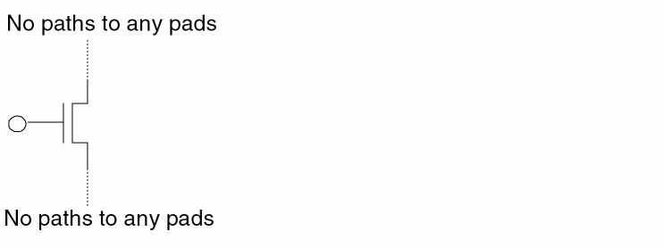
Filters out the MOS device if the gate is floating or does not connect to any pad through a source/drain path and either the source or drain net is floating.
An asterisk (*) denotes a floating node. An open circle (o) denotes a node that is not significant to the filtering criteria.
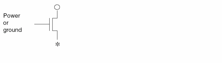
Filters MOS devices if the gate connects to a pad and either the source or drain net is floating.
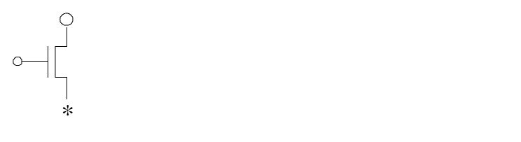
Filters out the MOS device if the gate connects to power or ground and either the source or drain is floating.
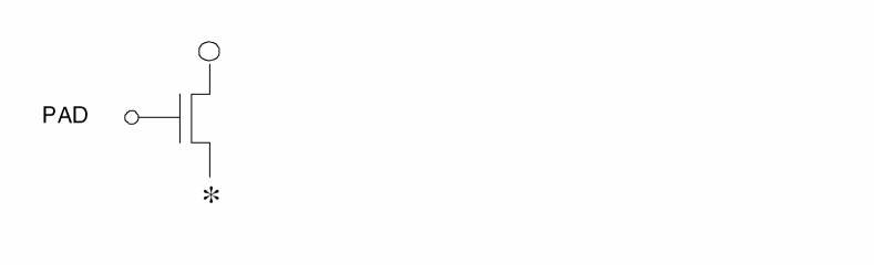
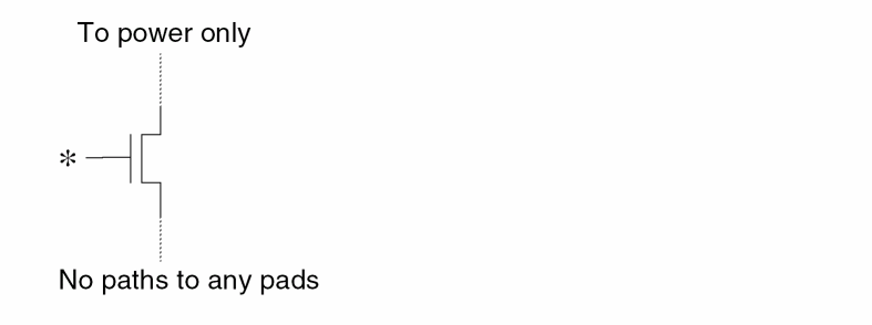
Filters out the MOS device if the gate is floating and the source/drain nets have only a power path and no paths to any other pads.
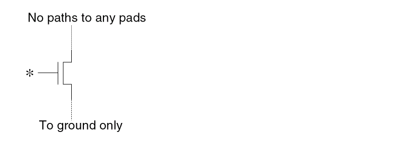
Filters out the MOS device if the gate is floating and the source/drain nets have only a ground path and no paths to any other pads.
Filters MOS[N] devices that have the gate tied to a ground.
Filters MOS[N] devices that have the gate connected to ground, then reconnects the source and drain terminals after the device has been filtered out. If the source and drain connect to two different pads, then no reconnect occurs and a warning message appears.
Filters MOS[P] devices with the gate tied to power.
Filters MOS[P] devices that connect the gate to power, then reconnects the source and drain terminals after the device has been filtered out.
If the source and drain connect to two different pads, then no reconnect occurs and a warning message appears.
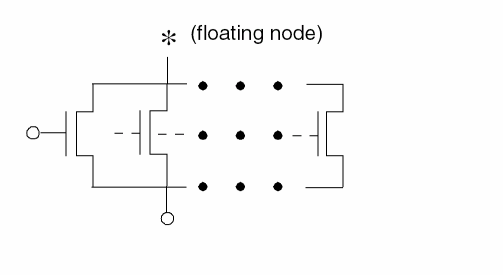
Filters series MOS devices when both the source and drain have a path to power.
The following structure is filtered out by H option but is kept by H’ option.
Filters series MOS devices when both the source and drain have a path to ground.
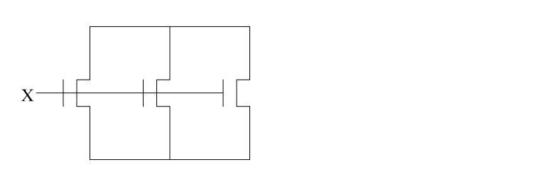
Filters MOS devices with the gate tied to either power or ground and source and drain tied together.
Filters MOS devices with source and drain having no paths to any pad.
Filters MOS devices if either the source or drain is floating.
Filters MOS[P] devices if the gate connects to ground, then reconnects the source and drain terminals after Dracula filters out the device. You can specify an asterisk (*) after the P to filter out MOS devices with any character following the P (MOS[P*]).
Filters MOS[N] devices if the gate connects to power, then reconnects the source and drain terminals after Dracula filters out the device. You can specify an asterisk (*) after the N to filter out MOS devices with any character following the N (MOS[N*]).
Repeats the FILTER process until there are no devices to be filtered under the options specified.
Filters out devices with no general paths to any pads. Note that general path is used here to distinguish it from the source-drain paths of MOS devices. A general path can go through any terminal of a device. A source-drain path can only go through the source and drain terminals of a MOS device. The P option filters all groups (islands) of devices that are isolated from all pads.
Filters out devices with no general paths to any nonpower/ground pads. (See option P for the definition of a general path.) This option filters all groups (islands) of devices that are isolated from all pads, except possibly power/ground pads. By definition, all devices filtered by P option are filtered by Q option. You cannot use the two options at the same time.
Filters out capacitors, resistors, and diodes with at least one floating terminal.

Filters out BJT devices with at least two floating terminals.
Filters out BJT with emitter and collector that connect together and do not connect to other devices.
Filters out MOS devices if both the source and drain are floating.
Filters out MOS devices if the following is found:
The gate is floating, and the source or drain is floating, and the non-floating terminal is connected to power or ground.
Filters out floating bipolar transistors, diodes, resistors, and capacitors.
Example 1
LVSCHK[F] initiates a preset filtering process that is equivalent to the following command sequence.
*DESCRIPTION
FILTER-LAY-OPT = BCDEFGHIJKO
FILTER-SCH-OPT = FGHIJKO
*END
LVSCHK[G] initiates a preset filtering process that is equivalent to the following command sequence.
*DESCRIPTION
FILTER-OPT = BCDEFGHIJKO
*END
Example 2
To set different filter operations, use the FILTER options commands. Remember that you must use LVSCHK or LPECHK [F] or [G] to activate the filtering process.
*DESCRIPTION
FILTER-LAY-OPT = DEFGHI
FILTER-SCH-OPT = FGHI
*END
*OPERATION
LVSCHK[F]
*END
FILTER-LDD
FILTER-LDD = YES/NO
Description
This command treats the LDD device as a regular MOS device, so all the FILTER options which apply to MOS will apply also to LDD.
Arguments
Turn off this function. NO is the default.
Example
FILTER-LDD = YES
FILTER-REPORT
FILTER-REPORT = ALL/{number}
Description
The FILTER-REPORT command in Dracula generates the information of filtered devices on the layout side in FILTERL.LIS and on the schematic side in FILTERS.LIS.
Arguments
Report all filtered devices for both layout side and schematic side to FILTERL.LIS and FILTERS.LIS.
Report the first {number} of filtered devices for both the layout side and schematic side to FILTERL.LIS and FILTERS.LIS.
Example
FILTER-REPORT = ALL
DevTyp   DevNum  X      Y       FilOpt  Terminals
MOS      25      19.60  245.55  G       1  17  246
MOS      26      25.50  245.55  G       1  17  246
MOS      27      41.80  245.55  G       1  18  246
MOS      28      47.70  245.55  G       1  18  246
MOS      29      64.00  245.55  G       1  19  246
DevTyp   DevNum  ----   ElmNam        FilOpt  Terminals
MOS      3       ----   MXN72XI71XI3  F       6  6   14
MOS      9       ----   MXN82XI71XI3  G       3  15  3
MOS      39      ----   MXP131XI658X  G       2  37  2
MOS      46      ----   MXP22XI1      G       2  10  17
MOS      47      ----   MXP78XI1      G       2  2   21
FIX-INPUT-ORDER
FIX-INPUT-ORDER = INSTANCE/EXCEPT-LOGIC/YES/NO
Description
Controls the swapping of logic gates and series/parallel structures. For information about including this information in the netlist file, refer to the
The FIX-INPUT-ORDER command might affect backannotation. Although a resistor for an internal node might be assigned a different schematic name, the number of parasitic resistors and their relative locations remain the same.
Arguments
Instance swapping is controlled by specifying individual or subtype non-swappable MOS devices in the circuit netlist files.
Swaps only inputs to logic gates.
Specifies that MOS transistors are not swappable.
Smashes all split gates and forms complex structures. Default.
Examples
FIX-INPUT-ORDER = INSTANCE

FIX-INPUT-ORDER = EXCEPT-LOGIC

FIX-INPUT-ORDER = YES

FIX-INPUT-ORDER = NO
FLAG-ACUTEANGLE
FLAG-ACUTEANGLE = YES/NO
Description
Reports the coordinates of acute-angle polygons. This command works with the RESOLUTION command. RESOLUTION sets the grid step size.
FLAG-ACUTEANGLE reports polygons under “Problem Geometries” in PRINTF.sum file. This command processes the polygons and reports the x,y coordinates of the polygon vertices, the layer number, and the associated cell name. It checks the polygon in each cell structure (cell name) before merging the layout data.
Arguments
Example
FLAG-ACUTEANGLE = YES
FLAG-NON45
FLAG-NON45 = YES/NO
Description
Reports the coordinates of non-orthogonal lines (non 45-degree angles). This command works with the RESOLUTION command. RESOLUTION sets the grid step size.
FLAG-NON45 reports polygons under “Problem Geometries” in the PRINTF.sum file. This command processes the polygons and reports the x,y coordinates of the polygon vertices, the layer number, and the associated cell name. It checks the polygon in each cell structure (cell name) before merging the layout data.
Arguments
Flags non-45 degree angle polygons.
Example
FLAG-NON45 = YES
FLG-EXPTH-OFFGRD
FLG-EXPTH-OFFGRD = YES/NO
Description
Flags the coordinates of a non-orthogonal exploded path that are offgrid. This command works in conjunction with the values specified in the SCALE and RESOLUTION commands.
Arguments
Flags the coordinates of the exploded path that are offgrid.
Does not flag the coordinates of the exploded path that are offgrid. NO is the default.
Example
In the following non-orthogonal path, assume that the centerline coordinates are on-grid and the width of the path is an integer multiple of the RESOLUTION value.
Unless the RESOLUTION value is set equal to the SCALE value, the coordinates (a), (b), (c), and (d) will be technically offgrid when the path is exploded.
*DESCRIPTION
...
SCALE = 0.001 MICRON
RESOLUTION = 0.25 MICRON
...
FLG-EXPTH-OFFGRD = YES
...
*END
The coordinates (a), (b), (c), and (d) will be flagged as being offgrid in the summary file. The offgrid coordinates will be marked with an asterisk sign (*).
FLAG-OFFGRID
FLAG-OFFGRID = YES/NO {grid-value}
Description
Reports the coordinates of cell placements and polygons that have vertices off the grid. Works with the FLAG-PTH-OFFGRID and RESOLUTION commands. The RESOLUTION command sets the grid step size. To use a different grid, specify the grid-value.
FLAG-OFFGRID reports cell placements and polygons whose vertices are off the grid and off-grid cell placements under “Problem Geometries” in the PRINTF.sum file. This command processes the polygons and reports the x,y coordinates of the polygon vertices, the layer number, and the associated cell name. It checks the polygon in each cell structure (cell name) before merging the layout data.
Arguments
Flags all cell placements and polygons that are off grid.
If FLAG-OFFGRID = YES and FLAG-PTH-OFFGRID = YES, all cell placements, polygons, and paths that are off grid are flagged.
If FLAG-OFFGRID = YES and FLAG-PTH-OFFGRID = NO, only cell placements and polygons that are off grid are flagged.
Default. If FLAG-OFFGRID = NO and FLAG-PTH-OFFGRID = NO, no off-grid checks are done.
If FLAG-OFFGRID = NO and FLAG-PTH-OFFGRID = YES, only paths that are off grid are flagged.
Specifies the grid. Value must be a real number greater than 0.0 but, less than 1.0.
Example
FLAG-OFFGRID = YES 0.1
...
L1 = 6 OFFGRID = 0.01
FLAG-PTH-OFFGRID
FLAG-PTH-OFFGRID = YES/NO
Description
Reports the coordinates of paths that have vertices off the grid. This command works with the FLAG-OFFGRID command.
FLAG-PTH-OFFGRID reports the x,y coordinates and the layer of the paths whose vertices fall off the grid under “Problem Geometries” in the PRINTF.sum file.
Arguments
Flags all paths that are off grid.
If FLAG-PTH-OFFGRID = YES and FLAG-OFFGRID = YES, all cell placements, polygons, and paths that are off grid are flagged.
If FLAG-PTH-OFFGRID = YES and FLAG-OFFGRID = NO, only paths that are off grid are flagged.
Default. If FLAG-PTH-OFFGRID = NO and FLAG-OFFGRID = NO, no off-grid checks are done.
Example
FLAG-PTH-OFFGRID = YES
FLAG-SELFINTERS
FLAG-SELFINTERS = YES {FULL}/NO
Description
Reports the coordinates of polygons that have self-intersecting vertices. This command works with the RESOLUTION command. The RESOLUTION command sets the grid step size.
FLAG-SELFINTERS reports polygons under “Problem Geometries” in the PRINTF.sum file. This command processes the polygons and reports the x,y coordinates of the self-intersecting vertices, the layer number, and the associated cell name and checks the polygon in each cell structure (cell name) before merging the layout data. This command requires moderate CPU resources for the EXPAND module.
If you specify FLAG-SELFINTERS = YES FULL, Dracula flags polygons that twist and are reentrant as illegal. For example, the following polygon contains a twist and is reentrant.
If you do not specify the full option, Dracula does not report this as an illegal polygon. If you do specify the full option, Dracula reports the polygon as illegal and lists its coordinates in the .sum file.
Arguments
Flags self-intersecting polygons.
Example
FLAG-SELFINTERS = YES
The following figure shows self-intersecting and reentrant polygons.
FLAG-SELFTOUCH
FLAG-SELFTOUCH = YES/NO
Description
Reports the coordinates of polygons that have touching vertices. This command works with the RESOLUTION command. The RESOLUTION command sets the grid step size.
FLAG-SELFTOUCH reports these polygons under “Problem Geometries” in the PRINTF.sum file. This command processes the polygons and reports the x,y coordinates of the touching vertices, the layer number, and the associated cell name and checks the polygon in each cell structure (cell name) before merging the layout data. This command requires moderate CPU resources for the EXPAND module.
Arguments
Example
FLAG-SELFTOUCH = YES
The following figure shows a self-touching polygon. Self-touching polygons are not processed.
FLAT-GDS-SMALL
FLAT-GDS-SMALL=YES
Description
Searches for small cells such as CONTACT or VIA in the given GDS2 stream file, and flattens them one level. This reduces the temporary files of the Dracula EXPAND stage and by reducing the temporary file size, sometimes improves speed.
The FLAT-GDS-SMALL command is best used with large designs where contact or via are defined as a "Cell".
Arguments
Expands small cells into polygon format in Interface stage.
Examples
SYSTEM = GDS2

FLAT-GDS-SMALL = YES
FLATTEN-PWRGND
FLATTEN-PWRGND = NO/YES
Description
Explodes the cell power or ground onto the composite plane to detect shorts formed between cell and composite levels.
If you digitize text directly down to cells without passing through the composite plane, you can cause shorts involving power or ground. This command flattens the cell power/ground text back onto the composite plane to detect these shorts. Be sure that the cell power or ground has the same name as originally used on the composite plane.
Checking Method
Arguments
Explodes power/ground onto the composite plane.
Example
FLATTEN-PWRGND = YES
FNODE-CONNECT
FNODE-CONNECT = [SubType1{,SubType2...}]Power_Pad1{,[SubTypeN{,SubTypeX..}],Power_Pad2.....}
Description
When Dracula runs selective LPE with SMART-LPE=SINGLENET, the source/drain of the selected loading devices mright be connected to nodes that become floating in the resultant SPICE netlist. Use the FNODE-CONNECT command to connect these nodes to power or ground so that the timing analysis can be done with the SPICE output .
Arguments
The subtype of loading devices connected to nodes that become floating.
Power/Ground nodes with which the floating nodes are to be connected.
Examples
FNODE-CONNECT = [N/NA] VSS, [P,PA] VDD, [NN] VSS1, [PP] VDD
When SMART-LPE=SINGLENET and the selected node is A, the netlist is reported as the figure. If M3 is a P type loading device, it connects node C and D to VCC. If M3 is NMOS, it connects node C and D to VSS.
GATE-RES-EXT
GATE-RES-EXT = [subType1] [subType2]
Description
Turns on gate resistance extraction. This command explicitly specifies which subtype of MOS extracts gate resistance. You can also use GATE-RES-EXT = ALL. This specifies that all subtypes extract gate resistance.
If both sides of the gate are connected, as shown below, the parasitic resistance of the gate is R.
The original netlist looks like the following:
net1 net2 net3
O--/\/\/\/\----O----\/\/\/\/\----O
R(res1) R(res2)
After gate resistance compensation, the netlist looks like the following example:
net1 net2 net3
O--/\/\/\/\----O----\/\/\/\/\----O
R(res1)+R/2 R(res2)+R/2
Parasitic gate resistance is evenly distributed to its adjacent resistors.
Arguments
Enumeration list of subtypes that perform gate resistance extraction.
Example
...
PARSET USER ANG W1 W2 AREA L W R ; add R parameter
GATE-RES-EXT= [N],[P]    ; specify interested
;   ; subtype
...
*END
*OPERATION
...
OR PGATE NGATE GATE
OR GATE POLTM PTRM
;
CUT-TERM POLY CNT PYRES PYTRM PTRM ; gate layer must be specified
CUT-TERM ME1 CNTVIA ME1RES ME1TRM
ELEMENT MOS[N]  NGATE  PYTRM  NSD  COPWL    ;PWELL
ELEMENT MOS[P]  PGATE  PYTRM  PSD  CONWL    ;NWELL
PARASITIC  RES[PY]  PYRES   PYTRM
ATTRIBUTE  RES[PY]  0.01
PARASITIC  RES[M1]  ME1RES  ME1TRM
ATTRIBUTE  RES[M1]  0.01
LEXTRACT USER NGATE NSD BY MOS[N] AAA &
EQUATION W= (1-ANG/60*0.02)*(W1+W2)/2 &
EQUATION L= AREA/W &
EQUATION R= 0.723* W/L    ; gate resistance is extracted
LEXTRACT USER PGATE PSD BY MOS[P] BBB &
EQUATION W= (1-ANG/60*0.07)*(W1+W2)/2 &
EQUATION L= AREA/W &
EQUATION R= 2.723* W/L    ; gate resistance is extracted
GEN-TEXT-FILE
GEN-TEXT-FILE = filename
Description
Specifies whether Dracula automatically texts the Hcells. At the same time, this command specifies the name of the file that contains the GEN-TEXT generated text. Use this file as the HEDTEXT file in cell or composite mode HLVS or HLPE runs.
After a GEN-TEXT run completes, the named file contains all Hcell text information, including the initial text from the layout (initial correspondence text).
Checking Method
Arguments
Name of file that contains the generated text. The file name can include a path name. The maximum size for path name or file name is 128 characters.
Example
The following example generates a text file to be used by the HEDTEXT or EDTEXT command.
GEN-TEXT-FILE = cell.htx
GEN-TEXT-FLTNODE
GEN-TEXT-FLTNODE = YES/NO
Description
Specifies whether floating nodes or feedthroughs are assigned text by GEN-TEXT. If you have feedthroughs within Hcells, you must specify GEN-TEXT-FLTNODE = YES. Otherwise, Dracula generates many discrepancy errors when running composite mode HLVS or HLPE. HLVS and HLPE handle these text names differently from other text nodes because they do not appear in the netlist version of the Hcell.
Checking Method
Arguments
Specifies that floating nodes be assigned text by GEN-TEXT.
No nodes are assigned text. Default.
You can text feedthroughs with a text name of the form, FTHRU#, with # being a number (for example, FTHRU44).
Dracula issues an error message if connected and soft-connected layers are not separable. (They are mixed in the connecting sequence.)
Example
GEN-TEXT-FLTNODE = YES
GEN-TEXT-FRAME
GEN-TEXT-FRAME = value-size units
Description
Generates a frame inside the Hcell boundary for use with GEN-TEXT. This frame must correspond precisely in size to all frames specified by HCELL commands for the composite HLVS run.
If you specify GEN-TEXT-FRAME and FRAME BY in HCELL commands or in an Hcell file, the values you specify in the FRAME BY option take precedence. This maintains consistency between frame values you use in GEN-TEXT and frame values you use in composite mode LVS. Therefore, if you specify FRAME BY in HCELL commands, you do not need to specify GEN-TEXT-FRAME in cell mode GEN-TEXT.
Checking Method
Arguments
Specifies the dimensions of the frame by giving the distance from the edges of the Hcell box.
Natural database units in microns or mils.
If possible, HLVS creates the Hcell text within the frame dimension. If any nodes in the Hcell cannot be assigned text within the frame area, Dracula reports these nodes in the .lvs discrepancy report file.
Examples
GEN-TEXT-FRAME = 10 microns
HCELL = ALU ALU1 frame by 2
HCELL = PLUG PLUG
For ALU, the frame value of 2 is used. For PLUG, the frame value of 10 is used.
HCELL = ALU ALU1 frame by 2
HCELL = PLUG PLUG
For ALU, the frame value of 2 is used; for PLUG, no frame is in effect and the whole PLUG cell is used for GEN-TEXT.
GEN-TEXT-WIRE
GEN-TEXT-WIRE = YES/NO
Description
Specifies whether GEN-TEXT generates wire type information on text when it finds geometries that need to be marked as an Internal-Wire or a MustJoin wire type. GEN-TEXT generates wire type information by concatenating a semicolon (;) and a number to the appropriate text.
Checking Method
Arguments
Generates wire type information for Internal-Wire geometries or MustJoin wire types.
Example
GEN-TEXT-WIRE = YES
GEN-TEXT generates wire type information for Internal-Wire geometries or MustJoin wire types.
GEN-XRF-RPT
GEN-XRF-RPT = YES
Description
Forces Dracula to output device and node cross-reference files DEVXRF.DAT and NETXRF.DAT on demand.
FLAT mode. If CHECK-MODE is not FLAT, PDRACULA should output ERROR message.DEVXRF.DAT and NETXRF.DAT are not empty, that means old cross-reference files exist and Dracula will do nothing. Only when one or two files are empty or don’t exist will Dracula generate those reports again.Arguments
Will output DEVXRF.DAT and NETXRF.DAT files.
Example
/bin/rm -f FOR008.DAT
/bin/ln -s NETXRF.DAT FOR008.DAT
/bin/rm -f FOR009.DAT
/bin/ln/ -s DEVXRF.DAT FOR009.DAT
GROUND-NODE
GROUND-NODE =name1,name2...
Description
Specifies ground nodes on text in the layout or in EDTEXT. If you do not properly text a non-unique ground text string in the layout, this command converts the non-unique text string to ground (pad type G). It does not add new text.
You can specify an asterisk (*) as a wildcard character following the ground text string.
Arguments
Text to convert to ground (pad type G).
Examples
The following example specifies VSS1, VSS2, and GND as ground nodes:
GROUND-NODE = VSS1, VSS2, GND
The following example indicates that the VSS text string followed by any character is a ground text string:
GROUND-NODE = VSS*
HCELL
HCELL =cell-name{logic-name{FRAME BYvalue-size}}
Description
Specifies layout cells to be used as Hcells. An Hcell is a cell structure that is preserved in its cell form because it is used in many instances.
Checking Method
Cell, composite, and hierarchical.
Arguments
Name of the cell structure in the layout database that is used as an Hcell.
Name of the logic circuit in the schematic that represents the subcircuit description that is equivalent to the layout cell structure (Hcell).
Specifies the width of the inside border used to frame the cell. The units of value-size are specified by the SCALE command (microns or mils).
HDRC uses HCELL commands with its automatic selection algorithm to determine which layout cells to use as Hcells. The other checks use the HCELL command as the only way to determine which Hcells to use.
For HLVS you must give the logic-name parameter, which is the name of a cell in the schematic netlist that corresponds to the layout cell chosen as Hcell.
You can use multiple HCELL commands. You can also specify a number of Hcell specifications using the HCELL-FILE command.
You can use the FRAME option only for a composite mode HLVS run. The FRAME option specifies a rectangular boundary within the Hcell, which is “hollowed-out” for the Dracula run. The distance from the border of the frame to the border of the Hcell is established with the value-size parameter. Refer to the following figure, which is a diagram of an Hcell frame.
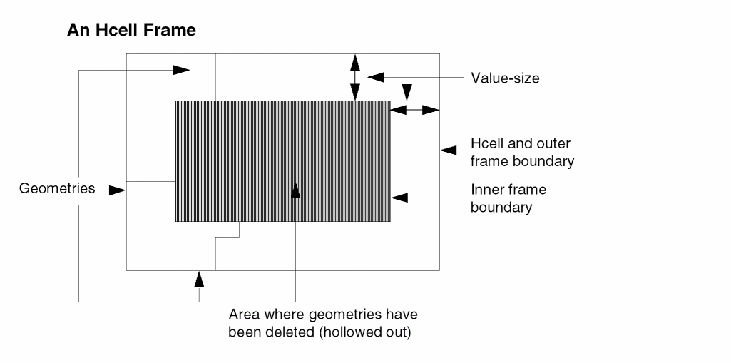
Dracula discards all geometries or portions of geometries inside the frame, thereby speeding up the composite HLVS run. The portions of geometries between the frame and the Hcell boundary remain to provide appropriate connectivity for the composite HLVS check.
When using a FRAME option, you must use wire types to text both ends of internal wires that have been disconnected by the frame. The GEN-TEXT operation provides this additional texting.
When using GEN-TEXT in conjunction with frames, you must specify that all frames defined by composite mode HCELL commands have the same dimensions as the frame specified in the cell mode GEN-TEXT-FRAME command. For more information, refer to the GEN-TEXT commands.
Examples
The following example is used for HLVS.
HCELL = alu alu1
The following example is used for HLVS.
HCELL = plug rom frame by 2
The following example is used for HDRC.
HCELL = plug
HCELL-COLUMN-1
HCELL-COLUMN-1 = LAY/SCH
Description
Specifies whether the first column in the Hcell table lists layout or schematic cells. For more information about the Hcell table, refer to the HCELL-FILE command description.
You must include this command in the Description block only if you run a schematic versus schematic (SVS) check with hierarchical Dracula. SVS requires two other commands as well: SVS-LAYOUT and SVS-SCHEMATIC.
Use this command in hierarchical Dracula only.
Checking Methods
Arguments
Type of cell names listed in the first column of the Hcell table. Type LAY for layout; type SCH for schematic. The default is LAY.
Example
To switch the role of the layout and schematic circuits after running LOGLVS, use the HCELL-COLUMN-1 command. For example, on the first LOGLVS run:
SVS-SCHEMATIC = LVSLOGIC.DAT
SVS-LAYOUT = ../LVSLOGIC.DAT
On the second run, to switch the circuits without rerunning LOGLVS, modify the rules this way:
SVS-SCHEMATIC = ../LVSLOGIC.DAT
SVS-LAYOUT = LVSLOGIC.DAT
HCELL-COLUMN-1 = SCH
HCELL-FILE
HCELL-FILE = filename
Description
Specifies a file containing a set of HCELL command statements. The format of each statement is the same as that of the HCELL command except that the keyword “HCELL =” is left out of each line. The statements in this file serve the same purpose as a group of HCELL commands. Use this command for HLVS runs (cell or composite mode) because LOGLVS, the network compiler, requires the same Hcell data as HLVS.
An Hcell file contains layout cell names, netlist cell names, and FRAME options. For example
HCELL = plug rom frame by 2
is equivalent to specifying an Hcell file with the following line
plug rom frame by 2
To connect layers that are not input-layers but that have geometries needed for texting, you can assign level numbers for the appropriate input-layers and use these input-layers for appending to the Hcells.
Checking Method
Cell, hierarchical, and composite.
Arguments
Specifies the name of the file containing the Hcell name descriptions. The file name can also include a path name. The maximum size for a path name or file name is 128 characters.
HCELL-IN-HCELL
HCELL-IN-HCELL = YES/NO
Description
Specifies that the instances of Hcells under parent Hcells flatten into transistors under the parent Hcells so that Dracula allows nested Hcells during hierarchical extraction.
Checking Method
Arguments
Specifies that if you have the following figure, where you specify A, B, and C are Hcells, and one cell B instance is under cell A,

both A and B remain Hcells and the instance B under A is exploded, which results in the following:

Default. No nested Hcells are allowed when running Dracula. If nested cells are found, Dracula issues a warning message. For example, in the following figure, if you specify A, B, and C as Hcells, the EXPAND stage aborts.

Dracula issues the following warning messages:
*/W* BOTH DESCENDANT AND ANCESTOR ARE SELECTED AS H-CELLS!
*/E* IT IS NOT ALLOWED IN COMPOSITE MODE, PLEASE CHECK THE
HCELL-FILE, OR USE <HCELL-IN-HCELL = YES>.
HCELL-MAX-PLACEMENTS
HCELL-MAX-PLACEMENTS = value
Description
Specifies a parameter for HDRC duplication of instance records. Use this command to avoid duplicating instance records when you select small cells with large numbers of placements as Hcells.
Checking Method
Arguments
Specifies the maximum number of cell placements a cell can have in order to be an Hcell.
Example
HCELL-MAX-PLACEMENTS = 600
HCELL-MAX-SEGMENTS
HCELL-MAX-SEGMENTS= seg-cnt
Description
Specifies a parameter for HDRC selection of layout cells as Hcells. Use this command to avoid selecting large cells as Hcells. For a detailed explanation of HDRC Hcell selection, refer to Chapter 3, “Checking Design Rules (DRC).”
Checking Method
Arguments
Specifies the maximum number of line segments required for a cell to be an Hcell candidate. Default is
MAX(L, total # of layers * 1,000,000)L = N / 256
Where N is the total number of line segments under the primary cell provided in the EXPAND module.
Example
HCELL-MAX-SEGMENTS = 5,000,000
HCELL-OPTIMIZE-PLACEMENTS
HCELL-OPTIMIZE-PLACEMENTS = value
Description
Specifies a parameter for HDRC duplication of instance records. Using this command avoid many duplicated instance records for single master cell that slow HDRC run.
Checking Method
Arguments
Specifies the maximum number of cell placements for master cell. Over this number, a new master cell created for other instance records.
Example
HCELL-OPTIMIZE-PLACEMENTS = 50
HCELL-RULE
HCELL-RULE =place-cnt1,seg-cnt1, {place-cnt2,seg-cnt2} {...}
Description
Specifies parameters for HDRC selection of layout cells as Hcells. For a detailed explanation of HDRC Hcell selection, refer to Chapter 3, "Checking Design Rules ERC" in this manual.
Checking Method
Arguments
Specifies the minimum number of cell placements required for a cell to be an Hcell candidate. Default is 2.
Specifies the minimum polygon segment count for a cell to be an Hcell candidate. You can specify multiple place-cntN, seg-cntN pairs. Default is four times the number of input layers.
Cells placed a number of times greater than or equal to the place-cnt parameter and having a number of segments (a rectangular polygon contains four segments) greater than or equal to the seg-cnt parameter qualify as Hcell candidates.
Place-cnt and seg-cnt act as requirement pairs. When multiple place-cnt, seg-cnt requirement pairs are specified, cells meeting any of the requirement pairs qualify as Hcell candidates.
To prevent any cells from being selected automatically, allowing you to direct selection of cells, you can specify a place-cnt and a seg-cnt of 9999, thus guaranteeing that no cell qualifies as an Hcell candidate.
Examples
In the following example, cells placed at least four times and having a minimum of 150 polygon edges are considered potential Hcell candidates.
HCELL-RULE = 4,150
In the following example, cells that either have been placed a minimum of four times and contain at least 150 polygon edges or that have been placed at least two times and contain a minimum of 300 polygon edges are considered potential Hcell candidates.
HCELL-RULE = 4,150 2,300
HIER-OUTDISK
HIER-OUTDISK = {outdisk-name}
Description
Specifies the name of the output file that contains error cells generated in the original design hierarchy. You must specify this command in the Description block when you include the CELL-ERROR-REP command with the ORIG-ALL, ORIG-DRC, or cell-name options.
Standard errors Dracula reports in the two-level hierarchy (the cell and composite planes) are still output to the file you specify using the OUTDISK command. If you use CELL-ERROR-REP, you have two output files. The output file specified by OUTDISK contains errors in the two-level Dracula hierarchy. The output file specified by the HIER-OUTDISK command contains the same errors in the original design hierarchy.
If you use CELL-ERROR-REP with the ORIG-ALL, ORIG-DRC, or cell-name option, but do not include HIER-OUTDISK, PDRACULA issues a warning and prompts for an output filename or uses the default name, HIEROUT.OUD.
Arguments
Specifies the output file name for layout error cells in the design hierarchy. Maximum path or file name is 128 characters.
IGNORE-SCH-SUB
IGNORE-SCH-SUB = YES/NO
Description
Ignores the schematic-side substrate in the SCHMIN stage.
Arguments
Sets the MOS substrate automatically in the schematic side to zero. The Dracula tool ignores this substrate whether you specify a substrate node in the netlist or not.
Is the default. This argument accepts the substrate in the schematic side. If you specify a substrate node in the netlist, the substrate takes effect in the SCHMIN stage.
INAME-TOPDOWN
INAME-TOPDOWN = YES/NO
Description
Specify the full path instance names in a flat spice netlist output by Dracula to be in top-down or bottom-up order of the hierarchy.
Arguments
Full path instance names are output in top-down order.
Full path instance names are output in bottom-up order. This is Default. Please notice that by default, full path instances generated by LOGLVS in file EXPELE.LIS is in bottom-up order.
Example
INAME-TOPDOWN = YES
INDISK
INDISK = {filename} {directory-name}
Description
Specifies the input file containing your layout. You must specify this command in the Description block.
Arguments
The input file name for a layout database. The maximum path or file name is 128 characters.
The directory containing Edge database blocks or a Design Framework II library.
If you assign a logical name and the name matches the file name you specify, the logical name has priority. You can use the logical name to refer to any disk file.
Examples
The following example specifies the directory name for Edge or DFII databases:
INDISK = /usr/project/data
This example specifies the input file name as myfile.DAT:
INDISK = myfile
This example specifies the input file name as 256K.DB:
INDISK = 256K.DB
This example specifies the input file name as 256K. (period (.) extension):
INDISK = 256K
INDISK-FILE
INDISK-FILE = filename
Description
Specifies the file containing the library paths to Design Framework II databases or the block paths for Edge databases. This file is required if you specify multiple Design Framework II library paths or multiple Edge block paths.
There are 2 sections to this command:
-
SYSTEM=CADENCE_44DD or SYSTEM=CADENCE
When SYSTEM=CADENCE_44DD, PDRACULA will not check the existence of the library paths defined in the INDISK-FILE. Thecds.libfile is used by the CDSIN44 module to find these paths. In version 4.9, the new CDSIN44 behaves as follows:-
If INDISK-FILE is set to a
cds.libfile, for exampleINDISK-FILE = /usr/projects/cds.lib
then CDSIN44 will use that file -
If
cds.libis in the current working directory, then CDSIN44 will use it. -
If neither of the cases given above apply, then CDSIN44 will search for
cds.libin directories defined in thesetup.locfile in the Cadence hierarchy. -
If no
cds.libfile is found, CDSIN44 will abort.
Example for SYSTEM=CADENCE_44DD:INDISK-FILE = /drac30/test/database/cds.lib
where the contents of thecds.libfile isDEFINE dracLib /net/cds123/usr1/home/data/dracLib DEFINE refLib /net/cds123/usr1/project/refLibs/stdCells
This specifies the path for the main library,dracLib, as well as any reference library paths that may be used bydracLib.
When SYSTEM=CADENCE_44DD or SYSTEM=CADENCE, the DFII license server program must be running on all workstations from which Dracula accesses DFII databases. Prior to IC 445, the DFII license server program was calledcdsd; after IC445 it became known asCLS(Cadence Locking System).
See the Cadence Application Infrastructure User Guide (chapter 11) for more information onCLSandcdsd.
For example, if you have DFII data on three workstations that are mounted to your workstation, when you use thedfcommand to list your disks you see:workstation1:/usr/libDir1 852847 714817 52746 93% /mount/libDir1 workstation2:/usr/libDir2 852847 714817 52746 93% /mount/libDir2 workstation3:/usr/libDir3 852847 714817 52746 93% /mount/libDir3
In your indisk.file, you have:./myLibDir /mount/libDir1 /mount/libDir2 /mount/libDir3
Thecdsd or CLSprogram must be running on workstation1, workstation2, and workstation3 in order for Dracula to access the DFII data. -
If INDISK-FILE is set to a
-
SYSTEM=OA
Similar to the C-level database access (CDBA), the Genesis II database or OpenAccess (OA) database is another Cadence EDA database infrastructure that allows designers to save their electronic designs into digital file format.
The major difference between the OA database and CDBA is that the OpenAccess database is designed to be open to or shared by all users so that it can be shared, accessed and perfected by the users.
In this release and subsequent releases, the Dracula product implements the modules OAIN to read and OAOUT to write in the OA database format. OAIN will read the OA database and translate (interpret) it into the data format that the Dracula product can understand. Similarly OAOUT will convert (translate) the Dracula polygon formatted data into the OA data format. OAIN and OAOUT work exactly the same way as CDSIN44 and CDSOUT.
Once SYSTEM = OA is defined in the rule file, PDRACULA interprets the commands in the rule files to invoke OAIN and OAOUT.
Before invoking OpenAccess, you must define these commands in the “Description Block Commands” section of your rule file:SYSTEM=OA
INDISK_FILE =
specified location for the libraryLIBRARY =
For more information on the OpenAccess database, see this website: http://www.openeda.org/index.html.name of the library directory
Arguments
The name of the file containing the paths to a Design Framework II or Edge database. Each line is a path to each database.
Examples
Example 1
INDISK = /net/cds123/usr1/home/data/dracLib
Specifies the path for the library dracLib.
Example 2
INDISK-FILE = /drac30/test/database/indisk.file
/net/cds123/usr1/home/data/dracLib
/cds/lib/cdslib
/cds/lib/schematic
Specifies the path to multiple libraries.
INSTPIN-FILE
INSTPIN-FILE[S] = instancePin
Description
Prints out instance pin information in ASCII format in the specified file. Use for composite mode only. The output file follows this structure:
TerminalName (X=xcoordinate Y=ycoordinate) SubnodeNet
Terminal name (pin name) on the Hcell
Signal name on the composite level after parasitic resistors are formed
Checking Method
Options
Specifies the backannotation naming convention.
Arguments
Example
In the following example, INV is an Hcell and TOP is the Primary block.
.SUBCKT  INV   Z  Y
...
.ENDS
.SUBCKT TOP  O   I
X1  A   I  /INV
X2  O   A  /INV
.ENDS
HPRE reports the following information to the output file instancePin:
X1 Y X=2.00 Y=4.00 #I:3
X1 Z X=4.00 Y=4.00 #A:2
X2 Y X=6.00 Y=4.00 #A:3
X2 Z X=8.00 Y=4.00 #O:2
Each line contains an instance pin's information:
- The first field is the cell instance name.
- The second field is the pin name.
- The third and fourth fields are the instance pin’s x,y coordinates.
- The last field is the node name of the instance pin connected with the hard-wired prefix '#'.
The convention of the node name is the original net name concatenated with the subnode-delimiter and subnode number.
The resulting SPICE file might look like the following:
.SUBCKT TOP O I
R1  I    I:2    1.80000E00
R2  I:2  I:3    1.20000E00
R3  A    A:2    2.00000E00
R4  A    A:3    1.50000E00
R5  O    O:2    1.40000E00
X1  A:2   I:3  /INV
X2  O:2   A:3  /INV
.ENDS
INTERNAL-NODE
INTERNAL-NODE =name1,name2...namen
Description
Specifies the names of internal nodes that are assigned text in the layout or in EDTEXT. If you do not properly text a non-unique internal text string in the layout, this command converts the non-unique text string into an internal node (pad type N). It does not add new text.
You can specify an asterisk (*) as a wildcard character following the power text string.
Arguments
Specifies internal nodes (pad type N).
Examples
In the following example, INET1, INET2, and INET3 are internal nodes:
INTERNAL-NODE = INET1, INET2, INET3
In the following example, the INET text string followed by any character is an internal node:
INTERNAL-NODE = INET*
INTERNODE-PREFIX
INTERNODE-PREFIX = " " or string
Description
INTERNODE-PREFIX lets you specify a prefix string for layout nodes that are not matched by LVS. In some cases, LVS does not match the internal nodes, and so the internal nodes are reported as unmatched. Also, the devices connected to the nodes are commented out due to unmatched terminals. By default, LPE/PRE reports nodes as the node name or the layout node number with the prefix “?” (question mark). INTERNODE-PREFIX reports the unmatched node as the node name or layout node number prefixed with a string that you specify. Connected devices are not commented out.
Arguments
One to four characters. The string cannot contain a space, a colon (:), a semicolon (;), or a question mark (?). If you specify a string longer than four characters, Dracula reports an error.
Example
INTERNODE-PREFIX = " " ; overwrites the prefix to be empty
M18150 N-9541_2 N-9721_10 4625 VDD P L=1.20U W=8.82U
M18151 N-9541_2 N-9720_2 4625 VDD P L=1.20U W=10.50U
M18152 4625 N-9724_6 I-9719-NP1 VDD P L=1.20U W=8.82U
*M18150 N-9541_2 N-9721_10 ?4625 VDD P L=1.20U W=8.82U
*M18151 N-9541_2 N-9720_2 ?4625 VDD P L=1.20U W=10.50U
*M18152 ?4625 N-9724_6 I-9719-NP1 VDD P L=1.20U W=8.82U
KCELL-FILE
KCELL-FILE = <kcell_filename>
Description
Specifies the cell name mapping file for the “Keep Cell Text” feature in LVS or SVS or LVL jobs.
KCELL-FILE has the same format as HCELL-FILE except that it only takes the first two columns. The first column specifies the cell name in the schematic side while the second column specifies the cell name in the layout side.
The file should be the same file which you specified in the LOGLVS command KCELL, if you are doing an LVS or SVS job.
“Keep Cell Text” is a feature that allows Dracula in the flat mode to keep the “Cell Text” in a full hierarchical mode which could help LVS or SVS or LVL in two aspects: accuracy and performance. For details about “Keep Cell Text,” see its Application Notes.
Checking Method
CHECK-MODE = FLAT
Arguments
Specifies the name of the file containing the Kcell name tables.
Example
KCELL-FILE = myKcell.tab
KCELL-FILE = /pathname/myKcell.tab
KEEPDATA
KEEPDATA = YES/NO/SMART/DRACULAINTERACTIVE/INQUERY
Description
Determines whether to save intermediate data files. The KEEPDATA command helps to control disk space usage by managing the Dracula binary-generated files that are created during the execution of a job. These files can have one of the following extensions on them: .CEL, .DAT, .ENC, .ENV, or .NDX. Either the user creates these files via the OPERATION block or the software creates these files for its own internal purposes.
You can specify any of these five values with this command:
Note:-
Unless you are restarting a Dracula job from the very beginning, it may not be possible to restart a Dracula job from any other stage if the
KEEPDATAcommand is set to eitherNOorSMARTorDRACULAINTERACTIVEeven if breakpoints are specified in the Dracula rules file. (Breakpoints you specify for theBREAKorRESTARTcommands become meaningless and either command ends the job). The only exception to this is when you are restarting a Dracula job from the exact stage where the job aborted due to a lack of computer resources (such as a lack of disk space). This is due to the fact that the input data.DATfiles needed by the stage where you are restarting the job may have been deleted during the previous run. -
The
KEEPDATAcommand does not delete the input files for the following commands when the run ends:INDISK,OUTDISK,SCHEMATIC, andEXPORTregardless of which value you specify for this command. -
Dracula distributed always runs with
KEEPDATA=YES, no matter what users specify. For a single CPU job,KEEPDATA=NOworks correctly. But, for a MULTICPU job, specifyingKEEPDATA=NOwill not delete intermediate files such as.DATafter you run jobs. - See the Dracula Distributed Processing and the Dracula Graphical User Interface Tool section in Chapter 2 of this manual.
-
Unless you are restarting a Dracula job from the very beginning, it may not be possible to restart a Dracula job from any other stage if the
Arguments
Saves all data files at the end of a run. This option does not delete any of the binary-generated files created during the execution of a Dracula job. This is the default value.
Deletes all the binary-generated files at the very end of the Dracula job. Do not use this option if you are planning to use the Dracula Interactive tool to display information or errors on your data.
Deletes a binary-generated file the moment it is no longer needed during the execution of a Dracula job. This option helps to use disk space as efficiently as possible. Do not use this option if you are planning to use the Dracula Interactive tool to display information or errors on your data.
Saves all the binary-generated files that are needed by Dracula Interactive in order to display information or errors on your data. Like the SMART option, this option also helps to use disk space as efficiently as possible during the execution of a Dracula job.
KEEPDATA=DRACULAINTERACTIVE works only for Dracula 4.8 users. KEEPDATA=INQUERY works for Dracula 4.7 (and lower than version 4.7) users.Example
KEEPDATA = SMART
KEEP-INST-FPIN
KEEP-INST-FPIN = YES/NO
Description
Keeps floating nets that are connected to cell instances, and also keeps floating Hcell pins in composite jobs. You can use this command if you have a schematic with both connected and unconnected pins and, in your layout, all the pins are not connected at the composite level. The KEEP-INST-FPIN = YES command does not discard these floating pins because the corresponding schematic HCELL pins are designated as floating pins.
See also Chapter 5 of this manual that contains the
Arguments
Does not filter out floating nets and floating Hcell pins.
Is the default. Filters out floating nets and floating Hcell pins.
Example
KEEP-INST-FPIN = YES
KEEP-SHORT-BJT
KEEP-SHORT-BJT = YES/NO
Description
Causes LVS to keep BJT transistors that have terminals connected to the same node. By default, LVS automatically removes such transistors.
Arguments
Does not remove the transistors.
Removes the transistors. Default.
KEEP-SHORT-CAP
KEEP-SHORT-CAP = YES/NO
Description
Causes LVS to keep capacitors that have terminals connected to the same node. By default, LVS automatically removes such capacitors.
Arguments
Does not remove the capacitors.
Removes the capacitors. Default.
KEEP-SHORT-DIO
KEEP-SHORT-DIO = YES/NO
Description
Causes LVS to keep diodes that have terminals connected to the same node. By default, LVS automatically removes such diodes.
Arguments
KEEP-SHORT-MOS
KEEP-SHORT-MOS = YES/NO
Description
Causes LVS to keep transistors that have terminals connected to the same node. By default, LVS automatically removes such transistors.
Arguments
Does not remove the transistors.
Removes the transistors. Default.
KEEP-SHORT-RES
KEEP-SHORT-RES = YES/NO
Description
Causes LVS to keep resistors whose terminals are connected to the same node. By default, LVS removes such resistors automatically.
Arguments
Does not remove the resistors.
Removes the resistors. Default.
KEEP-TEXT
KEEP-TEXT = YES/NO
Description
Output the text to all DRC output files and GDS output files
Arguments
Outputs the text to DRC output files
LAYER-FILE
LAYER-FILE = filepath
Description
Specifies the path to the directory containing the layer file. This command is mandatory for the Edge database.
Arguments
The path to the directory containing the layer file.
Example
LAYER-FILE = /drac30/test/layer
LAYER-FILE-TYPE
LAYER-FILE-TYPE = type
Description
Specifies the type of layer file. Use this command with the LAYER-FILE command for the Edge database.
LAYER-FILE and LAYER-FILE-TYPE add current to the path. The actual layer file is /.../.../layer/display/current (for example,
/drac30/test/layer/display/current).
Arguments
Specifies the actual representation of the layer file. The default type is display.
Example
LAYER-FILE-TYPE = display
LEGAL-CHAR-SET
LEGAL-CHAR-SET = character
Description
The default characters include A-Z, a-z, 0-9, +, -, *, /, (, ), #, ., <, >, _, ’, [, ], $, %, &, =, @. If you specify a LEGAL-CHAR-SET command, Dracula also considers those characters defined in that LEGAL-CHAR-SET command as legal.
Example
For Dracula to recognize the global signal name vdd!, gnd!, specify the special character ’!’ as
LEGAL-CHAR-SET = !
LIBRARY
LIBRARY = library-name
Description
Specifies the name of the Design Framework II library containing the primary cell in your design. You must include this command in the Description block if you include the command SYSTEM = CADENCE.
Arguments
The name of the Design Framework II library. Do not include the path name.
Example
SYSTEM = CADENCE
LIBRARY = ClassLib
LIMIT-DRC-ERROR
LIMIT-DRC-ERROR = YES/NO/{OUTPUT} number
Description
Restricts the number of DRC errors reported to a graphic or DRC output file. Use this command to conserve disk space. It works on flat, cell, composite, and hierarchical runs of DRC and HDRC.
Arguments
Outputs the first 100 DRC errors.
Outputs an unlimited number of DRC errors. Default.
If you turn this option on, then it only gives limitation for the OUTPUT polygon files while the trapezoid output files still contain all the errors.
If you turn this option on, it restricts the number of all DRC errors to be reported and outputs only a specific number of error violations. You cannot specify a number with more than nine digits.
Examples
LIMIT-DRC-ERROR = YES

LIMIT-DRC-ERROR = NO

LIMIT-DRC-ERROR = 10000
LIMIT-RUN-TO
LIMIT-RUN-TO = ALL {output-error-list-file} {output-modified-rule file}/error-cell-list-file
Description
PDRACULA finds all the error cells checked in the rule file and skips all rules when error cell checking did not occur. It writes the cell list to a file for further modification and generates a revised rule file for reference. Default file is ERRCEL.LIS under the current working directory. Default is NEWRULES in the current working directory. Each line represents one cell to be checked. It might be a subset of the file generated by the command option ALL.
Arguments
File containing all error cell names.
File containing rule deck run.
File containing the error cell list.
Example 1
*OPERATION
AND POLY PDIFF PGATE
NOT NDIFF NGATE NSD ; rule(1) : unused
NOT PDIFF PGATE PSD OUTPUT PSD 34
AND CONT POLY POLYCON ; rule(2) : unused
;
WIDTH METAL LT 3 OUTPUT XMET 40
SIZE[T] METAL BY 1 OUT MET1 1
*END
Example 2
LIMIT-RUN-TO = ALL
To find error cells in the rule file, skip rule (1) and rule (2), write the cell list to ./ERRCEL.LIS. The content of ERRCEL.LIS is
PSD34
XMET40
MET101
The content of the operation block of modified file NEWRULES is
*OPERATION
AND POLY PDIFF PGATE
;NOT NDIFF NGATE NSD
NOT PDIFF PGATE PSD OUTPUT PSD 34
;AND CONT POLY POLYCON
WIDTH METAL LT 3 OUTPUT XMET 40
SIZE[T] METAL BY 1 OUT MET1 1
*END
Example 3
LIMIT-RUN-TO = ALL /tmp/celllist
Same as example 2 except the output cell list is /tmp/celllist.
Example 4
LIMIT-RUN-TO = ALL /tmp/celllist NEW_RULES
Same as example 3 and all used rules would be stored in file NEW_RULES.
Example 5
LIMIT-RUN-TO = ERRCEL.LIS
Read cells from file ./ERRCEL.LIS.
Example 6
LIMIT-RUN-TO = tmp/celllist
Read cells from file /tmp/celllist.
LISTERROR
LISTERROR =number/YES/NO [PERCELL]
Description
Turns on the extended execution error listing for DRC or ERC runs. For runs on large ICs, this output can become large and unnecessary if your primary error investigation is graphic. The detailed listing of each DRC edge-pair violation and ERC trapezoid error output is in the log file or listing file. This command can also control the number of errors output for the antenna check. For more information, see the CHKPAR section in Chapter 13 of this manual.
For DRC edge-pair error violations, LISTERROR generates a detailed listing for the ENC, EXT, INT, WIDTH, and LENGTH commands. The listing is in the SPACING module. LISTERROR also generates a .drc file that lists the violation pairs.
The x,y coordinates in the log file or .drc file are relative to the origin of the cell name/structure name you specify with the PRIMARY command. The x,y coordinates in the .sum printfile under “Problem Geometries” are relative to the origin of the cell name/structure name containing the error shapes.
For ERC trapezoid error output, see the ERCSEL module or search for the error cell name (for example, drc401, float60, or shorts40).
Arguments
Prints the number of error violations you specify. Limit for number is four digits.
Prints the first 100 error violations.
Specifies the number of errors to be reported per cell. This option is not used in antenna checks.
Examples
LISTERROR = NO
LISTERROR = YES
LISTERROR = 1000
LISTERROR = 50 PERCELL
LONG-SUM-LEN
LONG-SUM-LEN = YES/NO
Description
Increases the line length of summary file, *.sum.
Arguments
Prints 130 characters per line for .sum file.
LOOP-TWO-CAP
LOOP-TWO-CAP = SERIES/PARALLEL
Description
Treats a two-device structure with connected terminals as either a series or parallel device after smashing. Dracula treats a loop of two capacitors as series/parallel capacitors. This means
node1 -> dev1 -> node2 -> dev2 - node1
To combine a loop of two capacitors to a single capacitor
Arguments
Treats the two-device structure as a series device after smashing. This is the default behavior.
Treats the two-device structure as a parallel device after smashing.
Example
LOOP-TWO-CAP = SERIES
LOOP-TWO-RES
LOOP-TWO-RES = SERIES/PARALLEL
Description
Treats a two-device structure with connected terminals as either a series or parallel device after smashing. Dracula treats a loop of two resistors as series/parallel resistors. This means
node1 -> dev1 -> node2 -> dev2 - node1
To combine a loop of two resistors to a single resistor
Arguments
Treats the two-device structure as a series device after smashing. This is the default behavior.
Treats the two-device structure as a parallel device after smashing.
Example
LOOP-TWO-RES = PARALLEL
LPE-FORMAT
LPE-FORMAT = LOGLVS
Description
For LPE/PRE output netlist, Dracula follow the convention of HSPICE as default. But adding this command in the Dracula rule file can switch to the format of LOGLVS(CDL).
Arguments
Prints the LPE/PRE output netlist in CDL format.
LPE-GROUND
LPE-GROUND = ground_name
Description
Lets you specify a unique ground name in multiple-ground cases if you want only one of them as ground node in the output SPICE file. It works on parasitic capacitance only. This LPE-GROUND command overwrites the LPESELECT[G] or SPFSELECT[G] commands. This command is case insensitive.
If you do not specify the preferred ground node name, then Dracula picks up the first ground node in the SPICE file as the lumped capacitance’s ground.
Arguments
LPE-PRECISION
LPE-PRECISION = n1
Description
Dracula outputs SPICE file with process precision to decimal point of n1 for device length and width. This command is only valid for layout only LPE job.
Arguments
LPE-QUERY
LPE-QUERY = CORE/EXPAND/ON {filename}
Description
Runs selective LPE for flat and composite modes.
Include this command in the DESCRIPTION block if you want LPE to extract the layout parasitics and devices associated with a particular path.
To run selective LPE, you must use two other commands:
For details about these commands, refer to the Description and Operation block chapters.
Arguments
Creates a final selected netlist that includes the user-specified nodes, the devices connected to the user-specified nodes, and the adjacent nodes connected to the terminals of the selected devices.
Creates a final selected netlist that includes both nets and devices reached from the nodes you specify, all nets and devices on traversed paths, and nets connected to selected devices that are not on the traversed paths.
Dracula creates the traversed path by starting from the user-specified nodes and passing the MOS/LDD source-drain connection, the BJT collector-emitter connection, the resistors, capacitors, and diodes. Dracula ends the traversed path on the input/output pins or the power/ground nodes and the gate terminal of MOS or the base terminal of BJT.
Writes selected node numbers and device numbers to filename. Other information is output to the log file. To prevent selected node numbers and device numbers from being output, specify the filename NoDump. If you do not specify a filename, selected node and device information is written to the log file.
Examples
In the following example, the user-specified node set is {I1}.
- Nodes on the traversed path (expanded from the user-defined nodes) = {I1, I2, I3}
- Adjacent nodes = {VDD, A, B, VSS, C, OUT}
- Selected devices = {P1, P2, N1, N2, P3, N3, N4}
The rule file for the LPE-QUERY example above might be the following:
*DESCRIPTION
LPE-QUERY = EXPAND
SELECT-MODE = SCH
...
*END
*OPERATION
NODE-SELECT = I1
...
*END
LUMPCAP
LUMPCAP = YES/NO/{subtype1,factor1 {subtype2,factor2} {subtype3,factor3}....}}/{ALL,factor}
Description
Lets you turn on lumped mode parasitic capacitance extraction for LPE and PRE jobs. By default (LUMPCAP=NO), Dracula stores parasitic capacitance as coupling in its internal binary file. You can use different reporting formats (coupling or lumped) when you output the capacitance in SPICE format with LISTLPE commands.
With the lumped mode option turned on, Dracula sums the capacitance of each node for every subtype and stores them as lumped (node to ground) in its internal binary files. You can use lumped format in LPESELECT commands only.
If you specify lumped mode, the parasitic capacitance binary parameter files occupy less disk space and total CPU time is reduced.
If you specify LUMPCAP=YES, you cannot specify the LPESELECT options C, T, P, and R. Dracula issues an error message if you specify these options.
You can also specify different multiplying factors for individual capacitance subtypes when lumping them to ground. This capability of Dracula can help achieve more accurate simulation.
Arguments
Turns on LUMPCAP mode. All subtype multiplying factors are 1.0.
Turns off lumped mode capacitance and uses the regular flow. Default.
subtype1,factor1 {subtype2,factor2}...
Uses different multiplying factors for their corresponding subtypes of capacitance. Uses the default multiple factor 1.0 for the other capacitance.
Uses this factor for all capacitances.
Example 1
LUMPCAP = A,0.2 B,1.0 C,1.5
Ct= Cg+0.2*Cc1+1.0*Cc2+1.5*Cc3
Dracula multiplies different subtype lump capacitances with their corresponding factors. If you don’t specify the factor for some capacitance subtypes, the default factor value is 1.0.
Example 2
LUMPCAP = ALL,2.0
The multiplying factor for all capacitances is 2.0.
LVL-PART
LVL-PART=SCHEMATIC
LVL-PART=GRAPHICS
Description
Alerts the preprocessor that you want to perform a layout versus layout (LVL) discrepancy check. PDRACULA processes the reference layout rules file first, then processes the target layout you want to check.
You can run the complete LVL job without breakpoints if you use the /NEXT command to combine the two LVL input rules files. You can also run two separate jobs. In either case, LVL-PART specifies the reference layout and the layout to check.
Examples
;LVL1.COM:           LVL2.COM:
*Description         *Description
.                    .
.                    .
INDISK= layout1.db   INDISK=layout2.db
PRINTFILE=LVL1PRT    PRINTFILE=LVL2PRT
LVL-PART=SCHEMATIC   LVL-PART=GRAPHIC
.                    .
.                    .
*END                *END
*INPUT-LAYER        *INPUT-LAYER
.                   .
.                   .
*END                *END
*OPERATION          *OPERATION
.                   .
.                   .
LVSCHK              LVSCHK
*END
To submit an LVL job, enter the following commands:
/GET LVL1.COM
/NEXT
/GET LVL2.COM
/FIN
LVL runs the lvl1.com file, then the lvl2.com file. The discrepancy report is named lvl2prt.lvl.
LVS-OPTION
LVS-OPTION = {options}
Description
Specifies the LVS error types to report.
Options
You can choose from the following options:
For an explanation of LVS error types, refer to Chapter 5, “Compiling Network Descriptions (LOGLVS)”.
If you do not specify an LVS-OPTION command, Dracula reports all errors. For a shorter LVS report, use LVS-OPTION. If after the initial run you want a different LVS report, use the LVS-OPTION command with the LVSRPT-ONLY command to generate and rerun the job from the LVSCHM module only.
The PRINTLINE and LISTUNMATCH qualifiers in the LVSCHK command still control the amount of output.
Example
The following example reports only matched device to unmatched node, unmatched schematic device, and unmatched layout device errors.
LVS-OPTION = BGH
LVSRPT-ONLY
LVSRPT-ONLY = YES/NO
Description
Generates a new LVS report from a previous LVS run. This command assumes that you saved files from a previous LVS run in the directory and want a different LVS report. Use this command with the LVS-OPTION command to generate the new report. Only the LVSCHM step is needed in the run.
Arguments
Generates a new LVS report from a previous LVS run.
Example
The following example reports only subtype mismatch and size mismatch errors. Dracula does not run the matching portion of LVS. If LVSRPT-ONLY is not present, Dracula runs both the matching and reporting portions of LVS, resulting in longer run times.
LVSRPT-ONLY = YES
LVS-OPTION = IJ
M-Factor Commands
MOS-M-FACTOR = WIDTH-LENGTH/NO
BJT-M-FACTOR = WIDTH-LENGTH/EMITTER-AREA/NO
RES-M-FACTOR = WIDTH-LENGTH/VALUE/NO
DIO-M-FACTOR = AREA/PERI/NO
CAP-M-FACTOR = AREA/VALUE/NO
Description
Evaluates the M-Factor tolerance commands you specified with LVSCHK or LPECHK. When you use M-Factor commands, for each group of parallel devices, Dracula checks the tolerances you specified and determines whether to merge the group in the circuit reduction phase.
The M-Factor commands tell Dracula to enable or disable M-Factor comparisons in the circuit matching phase. If you use an LVSCHK or LPECHK command with the K option ON and the S option OFF, Dracula ignores the M-Factor options.
To specify device M-Factors in a SPICE netlist, follow the SPICE/HSPICE conventions for specifying M-Factors. By default, Dracula recognizes schematic and layout devices without M-Factors as M-Factor = 1.
Arguments
Specifies to use device width and length tolerances to evaluate whether to merge the device. Dracula evaluates the tolerances you specify using the M-Factor Tolerance commands and does one of the following:
Specifies to use BJT device tolerances for emitter area to evaluate whether to merge a device.
Dracula evaluates the tolerances you specified using the M-Factor Tolerance commands and does one of the following:
Specifies to use DIO or CAP device tolerances for device area to evaluate whether to merge a device.
Specifies to use DIO device tolerances for periphery to evaluate whether to merge a device.
Specifies to use RES or CAP device tolerances for value to evaluate whether to merge a device.
Examples
MOS-M-FACTOR = WIDTH-LENGTH
BJT-M-FACTOR = EMITTER-AREA
M-Factor Tolerance Commands
MOS-W-TOLER = n1
MOS-L-TOLER = n2
BJT-EA-TOLER = n3
BJT-W-TOLER = n4
BJT-L-TOLER = n5
RES-W-TOLER = n1
RES-L-TOLER = n2
RES-V-TOLER = n3
DIO-A-TOLER = n4
DIO-P-TOLER = n5
CAP-A-TOLER = n6
CAP-V-TOLER = n7
Description
Indicates the number of separate devices, such as MOS or BJT devices, connected in parallel. You specify this number in a CDL netlist. If a MOS device contains four transistors connected in parallel, the multiplier you specify in your CDL netlist is M = 4.
You can use these M-Factor Tolerance commands with an LVSCHK or LPECHK command to specify tolerances for Dracula to use to determine whether a group of parallel devices reduces to a single device. If the group of n devices is within the tolerance value you specify using the M-Factor Tolerance commands, Dracula treats these devices as a single device with M-Factor = n. If the group of devices is greater than the tolerances you specify using M-Factor Tolerance commands, Dracula verifies them separately.
When you use the M-Factor Tolerance commands, for every group of parallel devices, Dracula checks the tolerances you specify and decides whether to smash the device group in the circuit reduction phase.
The M-Factor commands tell Dracula to enable or disable M-factor comparisons in the circuit matching phase. If you use an LVSCHK or LPECHK command with the K option ON and the S option OFF, Dracula ignores the M-Factor options.
To specify device M-Factors in a SPICE netlist, follow the SPICE/HSPICE conventions for specifying M-Factors. By default, Dracula recognizes schematic and layout devices without M-Factors as M-Factor = 1.
The M-Factor commands are as follows:
A MOS width tolerance you specify. This tolerance only works when you specify MOS-M-FACTOR = WIDTH-LENGTH.
A MOS length tolerance you specify. This tolerance only works when you specify MOS-M-FACTOR = WIDTH-LENGTH.
A BJT emitter tolerance you specify. You must also specify BJT-M-FACTOR = EMITTER-AREA.
A BJT width tolerance you specify. You must also specify BJT-M-FACTOR = WIDTH/LENGTH.
A BJT length tolerance you specify. You must also specify BJT-M-FACTOR = WIDTH/LENGTH.
A RES width tolerance you specify. This tolerance only works when you specify RES-M-FACTOR = WIDTH-LENGTH.
A RES length tolerance you specify. This tolerance only works when you specify RES-M-FACTOR = WIDTH-LENGTH.
A RES value tolerance you specify. This tolerance only works when you specify RES-M-FACTOR = VALUE.
A DIO area tolerance you specify. This tolerance only works when you specify DIO-M-FACTOR = AREA.
A DIO periphery tolerance you specify. This tolerance only works when you specify DIO-M-FACTOR = PERI.
A CAP area tolerance you specify. This tolerance only works when you specify CAP-M-FACTOR = AREA.
A CAP value tolerance you specify. This tolerance only works when you specify CAP-M-FACTOR = VALUE.
Examples
MOS-W-TOLER    = 0.1

MOS-L-TOLER    = 0.05

BJT-EA-TOLER    = 0.2

BJT-W-TOLER    = 0.01

BJT-L-TOLER    = 0
Default Tolerance Values
Dracula assigns a default M-Factor tolerance value when you do not specify an M-Factor tolerance in the run file. Two default values, tight-tolerance and loose-tolerance, are associated with each tolerance. Tight-tolerance means the values are required to be almost the same. Loose-tolerance means there are no constraints at all.
| Tight tolerance | Loose tolerance | |
You use the different default values in different situations, depending on whether MOS-M-Factor or BJT-M-Factor is specified in the run file.
MAG-BEF-GRID
MAG-BEF-GRID = YES/NO
Description
Switches the order of on-grid data placement and cell magnification. This command works with the RESOLUTION command. The default order of inputting layout data is as follows:
- Place the input geometry on grid.
- Magnify the input geometry according to the absolute magnification (as defined in the layout).
- Place magnified geometry on grid.
Arguments
Skips step 1, magnifying the input geometry before placing it on grid (scaled cell).
Example
This example skips step 1. This process is also known as “scaled cell.”
MAG-BEF-GRID = YES
MAGNIFY-IN
MAGNIFY-IN = factor
Description
Scales the data in a GDSII input database by the scale factor you specify. CONVERT-DATABASE must be present and set to YES.
Arguments
Specifies the scale factor. This floating-point number can have up to six digits after the decimal point.
Example
This example magnifies the data in the input GDSII database by 5 percent.
CONVERT-DATABASE = YES
MAGNIFY-IN = 1.05
MAGNIFY-OUT
MAGNIFY-OUT = factor
Description
Scales the data in a GDSII output database by the scale factor you specify. CONVERT-DATABASE must be present and set to YES.
Arguments
Specifies the scale factor. This floating-point number can have up to six digits after the decimal point.
Example
This example shrinks the data in the output GDSII database by 5 percent.
CONVERT-DATABASE = YES
MAGNIFY-OUT = .95
MAP-TEXT-FILE
MAP-TEXT-FILE = text.map
Description
Lets you map multiple text names to one name. For example, if you have multiple names on the same signal, you can use MAP-TEXT-FILE to make all the names equivalent. All names refer to the same signal without causing a “MULTILAB” or requiring re-texting of the layout.
You can map multiple names to one name on one line. For example, instead of
VDD1   VDD
VDD2   VDD
VDD3   VDD
VDD1 VDD2 VDD3 = VDD
You can also use wildcards in mapping. Only the question mark (?) and asterisk (*) are supported. A question mark (?) means a single occurrence of any character. An asterisk(*) means any number of occurrences of any character. For example,
VDD* = VDD
VDD? = VDD
Arguments
Example
*description
 MAP-TEXT-FILE= text.map
...
*end
text.map contains sets of equivalent texts:
----------------------------
text1 text2
text3 text2
text4 text5
...
----------------------------
MATCH-P-G-BY-TYP
MATCH-P-G-BY-TYP = YES/NO
Description
Forces Dracula to match power and ground nodes by name. By default, Dracula matches power and ground pads by type regardless of their names. This command turns off the default behavior.
Arguments
Matches power and ground pads by type. Default.
Matches power and ground pads by name.
Example
MATCH-P-G-BY-TYP = YES
MEMORY-CORE
MEMORY-CORE = DRAM/SRAM
Description
This command enables Dracula to recognize the most popular structure of memory core and can reduce it into a single device. Since the net itself is dramatically reduced, the performance of LVS is also improved.
The recognition of the DRAM or SRAM structures is limited to the following figures:
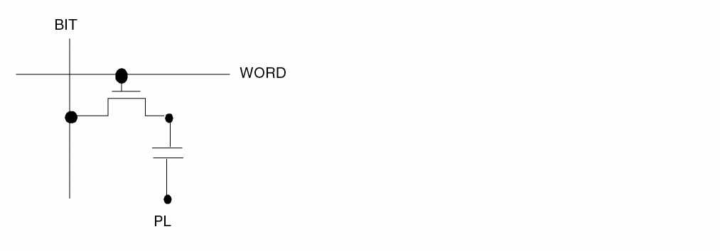
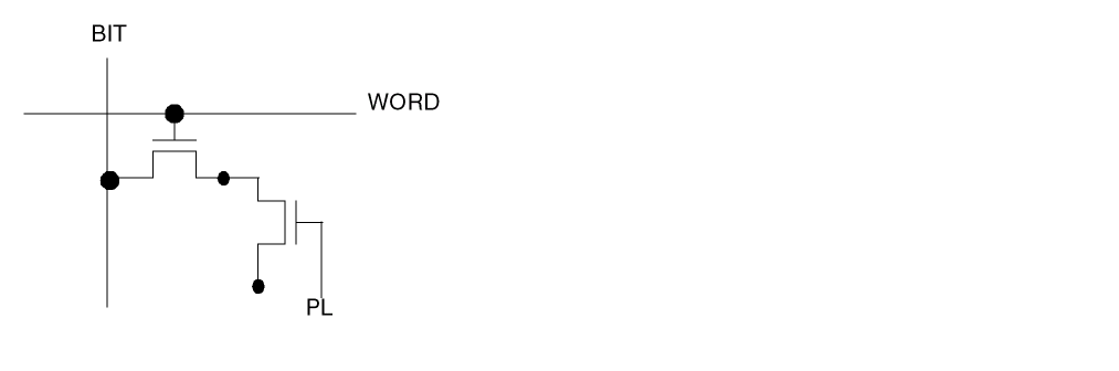
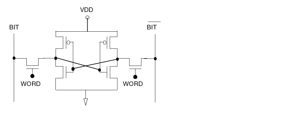
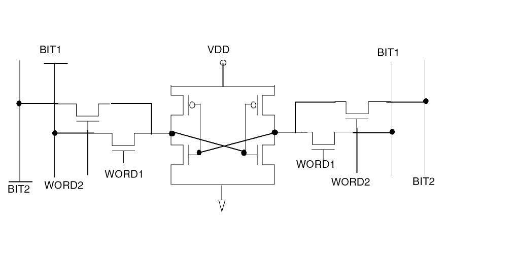
Arguments
Example
MEMORY-CORE = SRAM
MINI-SUMMARY
MINI-SUMMARY = YES {pattern1 pattern2 pattern3 ...}
Description
Greps data from <printfile>.log and <printfile>.msm. If you specify the command MINI-SUMMARY = YES, you get, by default, in the .log file:
| Symbol | Indicates |
|---|---|
To find other lines, you must specify them in the mini-summary line. “*/N*” stands for notational output messages. “*/L*” stands for listing output messages.
Example
MINI-SUMMARY = YES
MINI-SUMMARY = YES */N* */L*
MIRROR
MIRROR = option
Description
Flips a layout around the x or y axis.
Options
Mirrors along the horizontal or x axis.
Mirrors along the vertical or y axis.
Examples
The following example mirrors the layout database along the y axis.
MIRROR = Y
You can also use WINDOW and WINDEL commands with MIRROR. The MIRROR command affects the coordinates of the WINDEL and WINDOW commands in the same way.
WINDOW = 1000.  500.   2000.  2500.
WINDEL = 1500.  1500.  1800.  2000.
ROTATION = 90
MIRROR = Y
MODEL
MODEL = (layout-element,model-name...)
Description
Associates the MOS, BJT, and diode circuit elements with their corresponding circuit simulation model names. These model names appear in the SPICE-format listing generated by LPE.
You must specify this command for an LPE run. If you do not specify this command, LPE comments out all device references in the SPICE listing. You can repeat this command as needed.
Arguments
Specifies the user-defined layout element; that is, a MOS transistor (MOS), a diode (DIO), or a bipolar transistor (BJT).
Specifies the model name of the layout element in the circuit simulation (SPICE file).
Examples
MODEL=MOS[N],NCHNL...DIODE[N],NDIO...

MODEL=BJT[pn],pnp
MOS-CAP
MOS-CAP = P-G/NODE
Description
Recognizes MOS capacitors as MOSCAP devices. Dracula recognizes a transistor as MOSCAP when it meets one of the following conditions:
(1) Source and drain are connected to the same power/ground node.
(2) Source and drain are connect to the same node which is not limited to the power/ground node.
Arguments
MOS transistors with source and drain tied together to either power or ground.
MOS transistors with source and drain tied together to the same node.
Example
MOS-CAP = P-G
MOS-M-COMPARE
MOS-M-COMPARE = YES/NO/SCH-M-SET
Description
Enables or disables M-factor comparison during LVSCHM.
Arguments
Default. Will compare the M-factor for all MOS devices, including width and length.
Will not compare the M-factor, but will compare width and length.
Will compare the M-factor, including width and length, only when M-factor is set in the CDL.
Example
MOS-M-COMPARE = SCH-M-SET
MULTICPU
MULTICPU = CPU_NUMBER
Description
Allows you to use Dracula distributed processing in a multi CPU machine. This command is similar to the ?multiCPU command in the Assura product and you use this command for starting the Dracula distributed processing in a multiple CPU workstation.
When you specify the MULTICPU command in the Description block section of your rules file, PDRACULA creates the parallel file automatically.
Arguments
Specifies the number of CPUs. PDRACULA turns on the Dracula distributed processing. The Dracula product uses CPUs of this workstation for Dracula distributed processing.
draculaInteractive tool), see the “Note” under the “KEEPDATA” command section in this chapter and the “Dracula Distributed Processing and the Dracula Graphical User Interface Tool” section in Chapter 2 of this manual.MULTI-GDS2-IN
MULTI-GDS2-IN = filename CELL/LAYER
Description
Specifies the file containing multiple GDSII input files split by cells or layers. The 4.81 and 4.9 versions have a new feature, the layer shift option where if you need to deal with more than 2 input file layer cases, you should put a shift value in the input filename. This feature allows data to be read from multiple GDSII databases and still be maintained as separate layers even though the original data is on the same GDSII layer.
Arguments
File containing GDSII input file names. Input files can come in any order. You can specify files with absolute or relative paths. Wild card is not supported.
Indicates the GDSII files are split by cells or layers. CNAMES-CSEN is automatically turned on when the MULTIPLE-GDS2-IN command is used.
Examples
Example 1
MULTI-GDS2-IN = inFile CELL
The contents of inFile could be
GDSIIFile1.gds
/data/GDSIIFile2.gds
/usr1/Dracula/data/GDSIIFile3.gds
Example 2
MULTI-GDS2-IN = inFile LAYER
You can add a shift value in inFile as follows:
inFile:
    gdsin1.gds SHIFT 10
    gdsin2.gds
    gdsin3.gds SHIFT 20
You shift all layers in gdsin1.gds by 10, gdsin3.gds by 20, and there is no shift for gdsin2.gds. Data is merged if there is a layer number collision after the shift. You can provide a rule file for layers you need to manipulate with layer assignment based on new layer numbers.
Example 3
Given below is an example with two GDSII files in the following configuration. This example clearly tells you that Dracula can separately manipulate the layers specified in the inFile, if you have properly set the needed layer in the INPUT LAYER of the rule file.
Two GDSII files: rev1.gds rev2.gds. The original layer assignments for this example are as follows:
NWELL = 1
ACTIVE = 5
POLY = 10
M1 = 15
V1 = 20
then use the following syntax:
MULTI-GDS2-IN = inFile LAYER
NWELL = 1
ACTIVE = 5
POLY = 30
M1 = 15
V1 = 20
rev1.gds
rev2.gds shift 20
Dracula will get all layers from rev1.gds unchanged, such as NWELL, ACTIVE, M1, and V1; and the POLY layer from rev2.gds, which involves shifting the layer number by 20.
Then in the rule file, set POLY to layer 30(original(10)+20) and leave all other layers unchanged.
MULTI-PIN-FILE
MULTI-PIN-FILE = filename
Description
Specifies the output file name for the pad coordinates reported in PRE flatten mode. You can choose the option of not shorting multiple pins into one subnode and reporting all multiple pins in the .SUBCKT header of the SPICE file.
PRE generates and reports multiple sub-pin names to the .SUBCKT statement for feedthrough nodes and externally connected nodes. You must define how many pins to create with the PAD-LAYER command.
- This command works only in flatten mode PRE.
- The FDELIMITER command has a higher priority than MULTI-PIN-FILE, which might cause conflicts.
- Because PAD-LAYER defines all pin locations, you must define the pins correctly in the PAD-LAYER command.
- CDL and EDTEXT are unchanged by the MULTI-PIN-FILE command.
- PRE does not shorten pins with the same layout node number. However, it assigns different pin names for these pins. (The original pin name is concatenated with a subnode delimiter and a subnode number.)
- The MULTI-PIN-FILE command generates an ASCII file named mpfile, which contains the pin name and its x,y coordinates. The context of this file is similar to that of the EDTEXT file.
- Multiple pin names are reported in the SPICE netlist (.SUBCKT statement), which is different from the original schematic netlist.
Arguments
Output file name for multiple pin names and coordinates
Example
*DESCRIPTION
      SYSTEM         = GDS2
      PRIMARY        = mychip
      INDISK         = mychip.gds
      OUTDISK        = PRE.GOUT
      SCALE          = .001 MIC
      RESOLUTION     = .1 MIC
      PRINTFILE      = PRE
      SCHEMATIC      = LVSLOGIC
      MODE           = EXEC NOW
      MODEL          = MOS[N],N MOS[P],P DIO[N],DN DIO[P],DP
      DIODESEQ       = A1,P1
      UNIT           = CAPACITANCE,PF AREA,P PERIMETER,U   RESISTANCE,K
      CNAMES-CSEN    = YES
      PROGRAM-DIR    = /DRACULA/4.0.f1hot/bin/
      MULTI-PIN-FILE = PINS.FILE
      *END
MULTIPLE-DISK
MULTIPLE-DISK = YES/NO
Description
Links different physical disks or disk partitions and uses them as an aggregate resource. The disks can be distributed over a network or be NFS mounted.
You create a text file (MDISKIO.TAB) that lists the mounting point and directory paths Dracula uses for linking disk space. One separate MDISKIO.TAB file must be created for each slave node. MDISKIO.TAB.1 is for the master node. MDISKIO.TAB.2 is for slave node 1. MDISKIO.TAB.3 is for slave node 2, and so on. Keep the MDISKIO.TAB file in the same directory as the jxrun.com file.
When you write your MDISKIO.TAB file, specify the mounting point for each disk to use in the first field. Specify the directory to hold data in the second field, and specify reserved disk space in the third field.
The first line in your file represents the first disk, the second line represents the second disk, and so on. The default for reserved space is 10 megabytes for the first disk. Designate numbers for the third, or reserve space field, in kilobytes. After the first disk or line, the default for reserve disk space is 0, so you must enter a value in kilobytes.
The MUTIPLE-DISK command has no control over generated text files. Text files are written to the first disk and can include the job log file, summary file, and generated SPICE/CDL/DSPF file. To prevent the job from aborting because text files have filled the file system, reserve a large space in the first disk.
- This command works for UNIX systems only.
- PDRACULA does not have a multiple disk capability.
- To enable multiple disk mode in LOGLVS, specify MDISKIO.TAB in the LOGLVS run directory.
- Do not specify the same disk as both a hard and soft mount.
- To add new disks to the MDISKIO.TAB and restart jxrun.com from the middle, add the additional mounting points and directory paths to the end of the MDISKIO.TAB. Do not insert additional mounting points and directory paths in the middle of the MDISKIO.TAB file.
- You cannot list the same disk in the MDISKIO.TAB file more than once.
- When you specify MULTIPLE-DISK = YES, Dracula run speed is slower.
- You must compile the rules file and specify MULTIPLE-DISK in the working directory of the first disk that appears in the MDISKIO.TAB file.
If you specify an absolute or relative path (any path containing a backslash “/”) with the OUTDISK command, MULTIPLE-DISK creates the output file under that path if it exists. If the path you specify does not exist or if you do not specify a path, the MULTIPLE-DISK command determines the location of the output file and shows the location of this file in the .log file.
Arguments
Tells Dracula to use the MDISKIO.TAB file to link multiple disk directories. If you issue this command and a MDISKIO.TAB file does not reside in the directory where the jxrun.com file resides, PDRACULA issues a warning. Dracula automatically turns off the MULTIPLE-DISK command if the MDISKIO.TAB file is not found.
Tells Dracula to not link multiple disk space. PDRACULA does not warn you if you specify MULTIPLE-DISK = NO in your run file and an MDISKIO.TAB file exists. Default.
Examples
The following example shows the mount point in the first field, followed by the working directory path:
/user1 /user1/blk/myname/LVS ;default disk space (10 MB)
The following example shows the mount point, working directory path, and reserve space field. In this example, 5000 kilobytes of disk space is reserved.
/user2    /user2/blk/myname/LVS 5000   ;user-defined disk space
                                       ;default disk space (0 MB)
The following example specifies 8 MB of reserved disk space where the default is 0.
/user3    /user3/blk/myname/LVS 8000   ;user-defined disk space
                                       ;default disk space (0 MB)
NO-SUB-TERM
NO-SUB-TERM =subType1{,subType2}{....}
Description
Generates spice netlist without substrate nodes for those MOS devices of specified sub-types in this command. This command only works when the substrate node is not defined in a rule file of a layout only run or LVS run but, without reported schematic names (“S” option is not on in LPESELECT).
Arguments
Subtype name of MOS devices as defined in the ELEMENT command.
Example
NO-SUB-TERM = N,P
.....
ELEMENT MOS[P] PDEVICE PCBIAS PDIFDE ; no substrate node
ELEMENT MOS[N] NDEVICE PCBIAS NDIFC
.....
LPESELECT MOS OUTPUT SPICE
NOT-HCELL
NOT-HCELL =cell-name1{cell-name2} {...}
Description
Specifies the layout cells that are not to be selected as Hcells. For a detailed explanation of HDRC Hcell selection, refer to Chapter 3, "Checking Design Rules (DRC)."
Checking Method
Arguments
Layout cell name not to be considered an Hcell candidate.
Examples
NOT-HCELL = old

NOT-HCELL = old,logo
NRX-EXTRACT
NRX-EXTRACT = MOS [subType] [accuracy = HIGH/QUICK/HIGH-PARALLEL]
distance {SHADE} {coefficient}
Description
Outputs the resistance value of MOS source and drain. Dracula extracts the source/drain resistance in terms of SPICE NRX parameters. The extracted resistance is a function of the overlap perimeter of the Source/Drain and Gate layers, and the distance to its closest contact.

Each gate-edge segment contributes to the final NRX value. The closest contact determines the distance, as shown in the following examples.
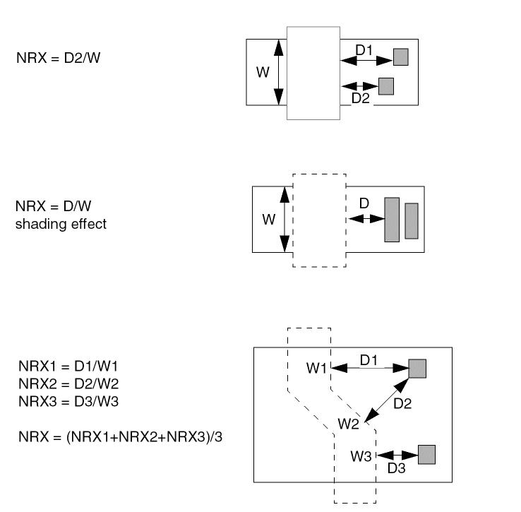
When you have more complex situations, for example, when contacts are not directly visible, or there is no contact, the distance is calculated as shown in the following examples.
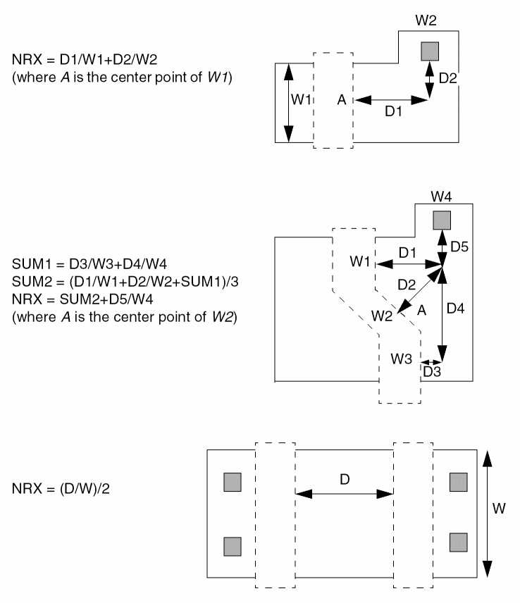
When parallel MOS devices are smashed, the equivalent NRX value is calculated as shown in the following equations:
For each source or drain, the equation is

To calculate the final NRX, the equation is

NRX Extraction With More Accurate Computation
In Dracula 4.81 and subsequent versions, you can get a more accurate computation for the NRX parameter in MOS source/drain resistance extraction (NRX-EXTRACT).
The existing computation of the NRX value in multiple gate edge case uses the average of Di/Wi as the final NRX value, where Wi is the width of each gate edge segment and Di is the distance from contact to its corresponding gate edge as shown in the following example. Assume that the coefficient is 1.
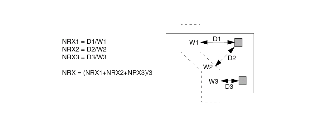
The three source/drain resistors in this example are actually connected in parallel. The total equivalent resistance value should be R = 1/(1/R1+1/R2+1/R3) (assuming that the three resistance values are R1, R2 and R3 respectively). So for the NRX extraction, a more accurate computation for the final NRX value for this example should be
NRX = 1/(1/NRX1+1/NRX2+1/NRX3)
Arguments
When you specify HIGH, the D value is extracted for each gate-edge segment.
When you specify QUICK, the D value is equal to the value you specify.
When you specify accuracy = HIGH-PARALLEL, the D value is of the same as accuracy = HIGH. If there are multiple gate edge segments, the final NRX value is computed as the following equation where n is the number of gate edge segments. The computation for each NRXi is still the same as the case of accuracy = HIGH.

NRX-EXTRACT = MOS[HN] HIGH-PARALLEL 0.0 1.0
If you specify accuracy of HIGH, distance is equal to the distance required to group contacts together. If the distance between the contacts is smaller than the distance value, the contacts are grouped together to make one contact. If the distance value is 0, there is no grouping.
When you specify accuracy = QUICK, the value is equal to the contact distance you specify. The value is used as D in the NRX calculation.
Optional argument you can specify when using accuracy = HIGH to take into consideration the shading of contacts.
The NRX equation, which is similar to the sheet resistance value. The default is 1 if you do not specify otherwise.
NRX = coefficient * Deff / Weff
You must follow these rules for calculating NRX:
When MOS devices are smashed, their equivalent NRX value is calculated by the following equations:
AREAi = NRXi * Wi * Wi
AREAtotal = SUM(AREAi) i=1,m
Wtotal = SUM(Wi) i=1m
NRXfinal = AREAtotal / Wtotal / Wtotal
Example
*Description
      NRX-EXTRACT= MOS[P] QUICK 1.0 2.1
      NRX-EXTRACT= MOS[N] HIGH 2.0 1.1
*End
*Operation
      element      mos[n] ngate   poly   nsd   pwell
      element      mos[p] pgate   poly   psd   nwell
*End
The extracted SPICE file might look as follows:
****** CORNER ADJUSTMENT FACTOR = 0.0000000******
M1    VSS  A  VSS  VSS  N_TF7_1  L=1.31U  W=16.00U  AD=104.70P  PD=45.09U
+     AS=130.30P  PS=48.29U  NRS=0.381  NRD=0.271
M2    VDD  A  VDD  VDD  P_TF7_1  L=1.60U  W=16.00U  AD=102.40P
+     PD=44.80U  AS=128.00P  PS=48.00U  NRS=0.131  NRD=0.131
NRX-SAVE
NRX-SAVE = value
Description
Control the format and precision of nrs/nrd (the resistance value of MOS source and drain) output, used in conjunction with NRX-EXTRACT command (refer to NRX-EXTRACT).
Arguments
Number of decimal places in the output. If value is negative, output is in IEEE format with number of decimal places equal to ABS(value).
Example
for nrs=12.34567
if NRX-SAVE=4, the output spice is nrs=12.3456;
if NRX-SAVE=-3, the output is nrs=1.234E+1
OAOUTTYPE
OAOUTTYPE = MARKER | POLY
Description
Specifies type of output OA22 data.
Arguments
Dracula saves output geometry to OA22 database as error markers. Error markers have no layer or purpose properties. In layoutPlus markers are visible by default.
Dracula saves output geometry to OA22 database as polygons and paths. This geometry will be visible in layoutPlus if these layer and purpose are defined in OA22 library’s technology file.
Example
OAOUTTYPE = MARKER
OAOUTTYPE = POLY
OPTIMIZE-RULE
OPTIMIZE-RULE = YES / NO
Description
Adding this command OPTIMIZE-RULE = YES / NO in your Description Blocks section of your rule file will let you optimize original rules and create more optimized rules to speed up your run time. This is a new feature in Dracula 4.81 and 4.9 versions and when you add this command in your Description Blocks section, PDRACULA automatically issues suggestions to you for optimizing your rule.
Arguments
Lets you optimize your original rule and speeds up your run time at least for those commands where you have tried to optimize the run time
Example
For examples, click on the following links which takes you to specific examples under their respective commands (SIZE, SELECT, OR, and NOT) in Chapter 13 of this manual for methods to optimize your original rule.
- SIZE: See the section, “Example 13 - Optimizing the Rule Using the SIZE Command” for more information.
- SELECT: See the section, “Example 2 - Optimizing the Rule Using the SELECT Command” for more information.
- OR: See the section, ““Example 2 - Optimizing the Rule Using the OR Command” for more information.
- NOT: See the section, “Example 2 - Optimizing the Rule Using the NOT Command” for more information.
OUTCELL
OUTCELL = cellname
Description
Specifies output top cell name in OA22 database. The default cell name is the same as defined by OUTLIB command.
Arguments
Example
OUTCELL = result
OUTCELL = outtopcell
OUTDISK
OUTDISK = filename
Description
Specifies the output file containing the error cells from the run. If INDISK and OUTDISK are the same, Dracula generates the output file with the same name but with a unique extension.
If you specify the output file with an absolute or relative path (any path containing a backslash “\”), the MULTIPLE-DISK command creates the output file under that path if it exists. If the path you specify does not exist or if you do not specify a path, the MULTIPLE-DISK command determines the location of the output file and shows the location of this file in the .log file.
See the MULTIPLE-DISK command in this chapter for more information.
Arguments
Output file name for layout error cells. Maximum path or file name is 128 characters.
Examples
In the following example, Dracula generates an output file named DRCOUT.DAT on disk.
OUTDISK = DRCOUT
OUTLIB
OUTLIB = cell-name
Description
Specifies the names for the output file library and the output primary name of the graphic output error cells for GDSII. The default output primary name is the input primary cell name you specify prefixed with OUT (that is, OUTcell name).
Arguments
Specifies the cell name for the output file. The maximum name size is 32 characters.
Examples
In the following example, the output library name is lib2.
OUTLIB = lib2
The output library name is fifo.ERR in the following example:
OUTLIB = fifo.ERR
In the following example, the output library name documents the date (February 29th, 1995).
OUTLIB = sram_2_29_95
In the following example, the output library name documents the circuit (1800 REV Z) and the date (April 1st, 1995).
OUTLIB = 1800_REV_Z_4_1_95
OUTPUT-ONE-LAYER
OUTPUT-ONE-LAYER= YES/NO
Description
Assigns all geometries associated with an error to one output layer.
Arguments
Assigns all geometries to one output layer.
Example
In the following example, all layers that make up shorted nodes are output on layer 25 only, instead of on multiple layers, such as metal to 25, poly to 26, and so on.
* DESCRIPTION
.
.
.
OUTPUT-ONE-LAYER = YES
* OPERATION
.
.
.
MULTILAB OUTPUT SHORTS 25
OVPR-TOLERANCE
OVPR-TOLERANCE = YES/NO
Description
Specifies a tolerance capability to resolve round-off errors occurring during layout parameter extraction. If you specify YES, the resolution value is automatically set to the scale value.
Arguments
Sets the resolution value equal to the scale value.
PARALLEL-FILE
PARALLEL-FILE = configuration-file
Description
Specifies the node configuration file to use in a distributed Dracula run. You create the node configuration file with a text editor such as vi or emacs. The node configuration file contains information about the nodes to be used in the run.
Include this command in the Description block if you are running distributed Dracula.
Arguments
The name of the configuration file.
Example
PARALLEL-FILE = machine.com
Node Configuration File
Each line in the node configuration file lists a node to be used in the run and contains the following six fields:
Name of the workstation to be used in the run.
Working directory on this workstation. The working directory must be different for each entry because no two workstations can share the identical disk space.
Node type. The possible values are 1, 0, and asterisk (*). For the master node, specify 1. For a slave node, specify 0 or *. The master node must be the first entry.
Dracula executable path for this workstation. An asterisk specifies the path listed by the PROGRAM-DIR command in the rules file.
Power rank of this workstation in relation to the other workstations being used in the run. The most powerful workstation has the highest number. An asterisk specifies a rank of one.
Mount type, which can be one of the following:
Sample Node Configuration File
iron    /dracula/test  1  *                        4 0
silicon /dracula/test  0  *                        3 0
nickel  /dracula/test  *  /net/nickel2/dracula/bin 3 0
In this example, nickel has an executable path that is different from the path specified in the PROGRAM-DIR command.
For more information about the node configuration file and how PDRACULA uses this file, refer to “Verifying a Design with Dracula”.
PAR-COMPARE
PAR-COMPARE = layout_box_element_name/
layout_parameter_name1, schematic_parameter_name1, tolerance1 /
layout_parameter_name2, schematic_parameter_name2, tolerance2 / ....
layout_parameter_nameN, schematic_parameter_nameN, toleranceN
Description
Triggers the LVS parameter comparison for box elements. This command specifies the corresponding schematic parameters to which each layout parameter should be compared to. PAR-COMPARE also defines the comparison tolerance for each pair of parameters.
Arguments
User-defined device name in the ELEMENT BOX command.
Schematic parameter name defined in the netlist.
The percentage tolerance for the comparison of a specified schematic/layout parameter pair.
Example
This example below defines an inductor as a box element on both the schematic and layout; the PAR-COMPARE command triggers the comparison of inductor parameters in LVS.
*.EQUIV IN1=spiral_rad
.SUBCKT spiral_rad T1 T2
.ENDS
.SUBCKT TEST1 P1 P2 P3 P4
X2 P1 P2 spiral_rad nr=4.5 rad=6e-05 w=1.5e-05 s=1.5e-06
X3 P3 P4 spiral_rad nr=3.5 rad=5e-05 w=1.5e-05 s=1.5e-06
.ENDS
*DESCRIPTION
.....
PARSET INDP ID IN IW IS LL
PAR-COMPARE = IN1/ID,RAD,5/IN,NR,3/IW,W,5/IS,S,6
....
*END
...
*OPERATION
...
ELEMENT IN1 ME5I ME4 ME5A
...
LEXTRACT INDP ME5I BY IN1 INDPAR&
EQUATION LL = ID+IN+IW+IS
The above example compares instances of the layout box element IN1 with instances of the schematic box element spiral_rad (from the *.EQUIV command). The PAR-COMPARE command triggers the LVS parameter comparison for instances of the box element IN1. The layout parameter ID is compared with the schematic parameter RAD, which has a 5% tolerance. The layout parameter IN is compared with the schematic parameter NR, which has a 3% tolerance.
PAROUTNAM
PAROUTNAM = pnamename1=param1[name2=param2...[namen=paramn]]
Description
Lets you define the names of parameters in your SPICE output.
Versions of Dracula prior to 4.81 reported the predefined parameters for specific element type only and you had no control on selecting or specifying which parameters are reported in the output SPICE file in Dracula LPE/PRE jobs. This prevented you from changing those parameter names after your Dracula LPE job and before you ran circuit simulation.
In Dracula 4.81 and subsequent versions, with this PAROUTNAM command, Dracula now:
- Lets you select or specify which parameters to be reported in the output SPICE file in Dracula LPE or PRE jobs
- Lets you specify the output names of the parameters
Arguments
Specifies the parameter set name. It must have been defined in a PARSET command, for example,
PARSET =pnameparam1param2..paramn.
Or, it’s a default PARSET, such as MOSD.
The user-defined output parameter name for the specified parameter in the PARSET. It will be output to the SPICE output. The user-defined output parameter name should be one to four alpha-numeric characters with the first character being alphabetic; otherwise, PDRACULA will output an error message:
**ERROR: ILLEGAL USER-DEFINED OUTPUT PARAMETER NAME .
The parameter name defined in the corresponding PARSET command,
PARSET =pnameparam1param2..paramn
You cannot use W;L as parameter names in PARSET for any elements except MOS elements (see Reserved Parameter Keywords in “PARSET”). To set up custom parameter names you must write symbols different from W or L (e.g. WS, LS, WM, LM...). See Example 3 below.
You can use PAROUTNAM to output user defined parameters, which are not specified for LPESELECT. In this case you should define the types of devices in LPESELECT to be used with PAROUTNAM. Example 4 below shows you how to output capacitance values for the parasitic capacitor “FC” using PARSET and user defined values ‘W’ and ’L’ for the canonical capacitor “PY” using PAROUTNAM and PARSET.
Examples
Example 1 - Output the Inductor Parameters
*DESCRIPTION
...
PARSET = TEST ID IN IW IS LL
PAROUTNAM = TEST ID=ID LSS=LL
...
*END
...
*OPERATION
...
ELEMENT IN1 INDSYM ME4 ME5
LEXTRACT TEST INDSYM BY IN1 PARAM1 &
EQUATION LL=-0.5+4*(ID/100)-0.9*IN
...
LPECHK
LPESELECT IN1 OUTPUT SPICE
...
*END
...
*
******
****** BOX Device PARAMETERS FROM : 7BOXXNET
******
*
*
XB34 6 5 / IN1 ID=29140.00 LSS=789.00
*
*----- TOTAL # OF BOX Devices FOUND : 1
*----- COMMENTED : 0
*
...
Example 2 - Output the MOS Parameters
*DESCRIPTION
...
UNIT = PERIMETER,U
MODEL = MOS[N],N
PAROUTNAM = MOSD LR=L WR=W
...
*END
*OPERATION
...
ELEMENT MOS[N] RBNGAT PLY NSD PSUB
...
LPECHK
LPESELECT MOS OUTPUT SPICE
...
*END
*
* CADENCE/LPE SPICE FILE : SPICE
...
M1 VSS A VSS VSS N LR=1.31U WR=16.00U
*----- TOTAL # OF MOS TRANSISTORS FOUND : 1
*----- COMMENTED : 0
*
.ENDS
Example 3 - Output the Resistor Parameters
PARSET MRPS AREA W1 W2 WS LS
PAROUTNAM MRPS LR=LS WR=WS
...
...
LEXTRACT MRPS prpip poly B Y RES[PS] RESPS &
EQUATION WS = W1 + W2 &
EQUATION LS = AREA/WS
****
**** RESISTORS PARAMETERS FROM: 7RESXNET
****
*
*
...
R605 7 8 RF_RNRPOS 2.47758E03 $W=0.17U $L=1.40U
R606 1 6 RF_RNS 6.27879E01 $W=0.17U $L=1.40U
R607 8 9 RF_RPRPOS 2.63879E03 $W=0.17U $L=1.40U
R608 6 7 RF_RPS WR=0.33000U LR=0.70000U
R609 9 10 ND 5.00606E02 $W=0.17U $L=1.40U
R610 INDAA 10 PD 1.12848E03 $W=0.17U $L=1.40U
*
*----- TOTAL # OF RESISTORS FOUND : 6
*----- COMMENTED : 0
*
Example 4 - Output User Defined Parameters for Capacitor.
..................
PARSET = NEWS TPR CLL AREA PERI OVPR C1 C
PARSET = CAPP AREA MIX WID LEN PERI
PAROUTNAM = CAPP L=LEN W=WID
................
PARASITIC CAP[FC] M1S2 BM1 PSUB
ATTRIBUTE CAP[FC] 1.876E-17 5.856E-17 0.9 3.386E-17
....................
ELEMENT CAP[PY] CP2CP POLY CP2CAP
..................
LEXTRACT NEWS M1S2 NS2 BY CAP[FC] FCT &
EQUATION C1=OVPR &
LEXTRACT NEWS M1S2 M1S2 BY CAP[FC] &
EQUATION C=1.876E-17*AREA+5.856E-17*(PERI-C1-TPR)+CLL
....................................................
LEXTRACT CAPP CP2CP POLY BY CAP[PY] SCA &
EQUATION MIX = SQRT(PERI*PERI-25*AREA) &
EQUATION LEN = (PERI+MIX)/4 -3*0.04 &
EQUATION WID = (PERI-MIX)/4 -3*0.04
.........................
LPESELECT[AG] CAP[FC] &
LPESELECT[AG] CAP[PY] OUTPUT SPIL
Example output of SPICE netlist:
******
****** CAPACITORS PARAMETERS FROM : 7CAPPFCC
******
*
*
CC1 GND GND 6.78957E-15
CC2 A GND 5.50732E-14
CC3 B GND 4.81427E-15
CC4 4 GND 9.95367E-16
CC5 6 GND 3.85104E-15
*
*----- CAPACITANCE TYPE : FC
*----- TOTAL # OF CAPS FOUND : 5
*----- COMMENTED : 0
*
******
****** CAPACITORS PARAMETERS FROM : 7CAPXNET
******
*
*
C1 B 4 LPE_C W=7.83000UM L=28.93000UM
*
*----- CAPACITANCE TYPE : PY
*----- TOTAL # OF CAPS FOUND : 1
*----- COMMENTED : 0
*
.ENDS
PARSET
PARSET =pname,param1,param2...paramn
Description
Specifies the names of a parameter set for a group of geometric primitives or computed parameters. To extract these geometric primitives and computed parameters, use the LEXTRACT and EQUATION commands in the Operation block. If you specify LEXTRACT, you must also specify PARSET.
Arguments
Specifies the parameter set name. Maximum length is four alphanumeric. The first characters must be a letter. Do not specify any of the following reserved names: MOSD, DIOD, DIO2, DIO3, CAPD, CAPF, BJTD, or RESD. Default parameter set name is CAPO.
Specifies the parameters in a set. The parameter limit is 18. PRE recognizes only the first ten parameter keywords and overwrites the last eight parameters with node and subnode information in order to save the data file size. The reserved parameter keywords used by SPICE must be limited to the first ten parameters. The remaining eight parameters can be used for LPE.
When you need to support inductors in layout designs, you must first use this PARSET command (in the description block commands section of your rule file) to specify what parameters will be extracted, followed by the ELEMENT IN? in the operation block of commands in your rule file. There are four geometric primitives regarding inductors provided: ID, IN, IW, and IS and one reserved parameter, LL.
See the section below for information these 4 primitives, ID, IN, IW, and IS and the parameter, LL.
See the ELEMENT IN? section in the “Operation Block Commands” chapter of this manual for more information on that command.
Parameters can be one of the following three types:
Primitives that relate to the layer or layers you specify in LEXTRACT. Extracted values relate to each device layer of layer-a in LEXTRACT. You cannot alter these primitives by using an equation. |
||
|
|
||
|
|
||
|
|
||
|
|
||
|
|
||
|
|
||
|
|
||
|
|
||
|
|
||
|
|
||
|
|
||
|
|
Diameter of the inner circle. It’s possible that the diameter of X-direction is different from that of Y-direction. Whichever is smaller will be selected. |
|
|
|
||
|
|
||
|
|
||
Keywords reserved for parameter values that relate to specific devices. You usually specify these keywords for CDL or SPICE simulations. You change these keywords by using an EQUATION command. |
||
|
|
||
|
|
||
|
|
||
|
|
||
|
|
||
|
|
||
|
|
||
|
|
||
|
|
||
|
|
||
|
|
||
|
|
||
|
|
||
|
|
||
|
|
||
|
|
||
|
|
||
|
|
||
|
|
||
|
|
||
|
|
||
|
|
Inductance of the inductor and it is calculated depending on the equation specified in the rule file associated with that particular element. See the “Supporting Inductors in Layout Designs Using the PARSET and ELEMENT IN? Commands” section in the “Extracting Electrical Parameters (LPE)” chapter of this manual for information on the different types of inductors. |
|
Names other than reserved parameter keywords. The maximum length is four alphanumeric characters. The first character must be a letter. |
||
Example
PARSET = TEST ID IN IW IS LL
PATH-W-OFFGRID
PATH-W-OFFGRID = YES/NO {grid-value}
Description
Checks whether the width of a path is off grid. Dracula checks whether the width of each path is a multiple of the grid size if paths expand on one or both sides. You can use a different grid by specifying a grid value.
Arguments
Specifies the grid to use. You must specify a real number greater than 0.0 but less than 1.0
Example
PATH-W-OFFGRID = YES
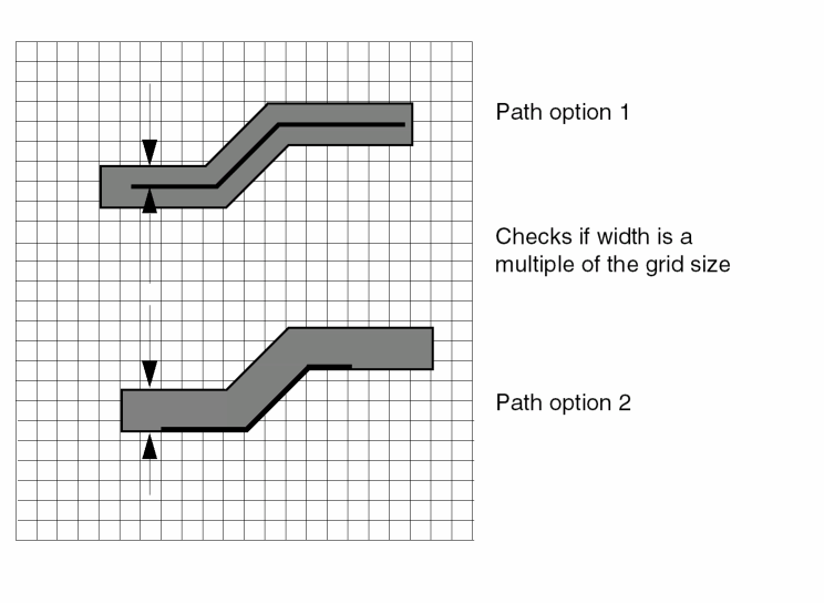
PATH-W-ROUND
PATH-W-ROUND = DOWN/UP/VIRTUOSO
Description
Finishes a non-orthogonal path by rounding the path width either up or down or in a Virtuoso manner.
Arguments
Rounds down the path width so that it is smaller than or equal to the true path width.
Rounds up the path width so that it is larger than or equal to the true path width.
Rounds the path width in a Virtuoso manner.
Examples
PATH-W-ROUND = UP
PATH-W-ROUND = DOWN
PATH-W-ROUND = VIRTUOSO
The SIZE or SIZE DOWN-UP commands produces false errors on a 45 degree path after converting it to a polygon. The Virtuoso layout editor and the Dracula tool calculate the coordinates of the path’s polygon in the different manner. The difference may be equal to approximately1 dbu (see the illustration below). The red-colored line represents the line that the Virtuoso layout editor produces.
If you want to see figures that are exactly the same as in the Virtuoso layout editor, you need to add the “convert path to polygon in a Virtuoso style" feature. You add this feature by turning on the Virtuoso mode to the round-off path using the Virtuoso layout editor (even if it’s not mathematically correct). The Dracula tool fixes the width of the polygon when building it, instead of saving the parallelism of two opposite edges of the path’s polygon in a Virtuoso manner. If the coordinates were floating point type, the result looks the same. But, since the coordinates are integers you get a difference of 1 dbu in some cases.
The Virtuoso-mode allows you to choose the method that is most appropriate for you.
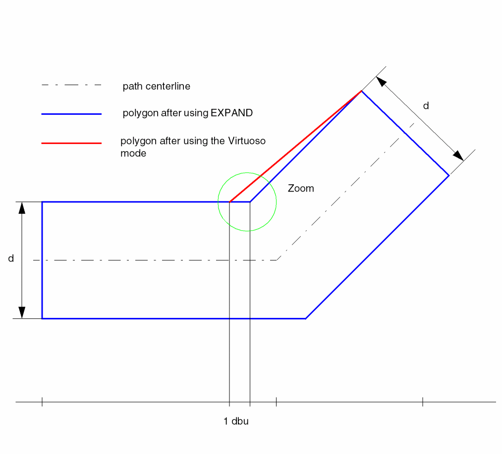
PINCAP-FILE
PINCAP-FILE = pincapfile
Description
Specifies the pincapfile, which contains the pin capacitance information in the form:
cellName1
pinName1   cap-value1
pinName2   cap-value2
cellName2
pinName1   cap-value1
pinName2   cap-value2
INV
IN         3.0
If you do not use this command to specify a pincapfile, the default capacitance value for all pins is zero.
Arguments
Name of the pin capacitance file.
Example
In the following example, pins in design are assigned the capacitance values specified in the design.pincap file.
PINCAP-FILE = design.pincap
POINT-CONNECT
POINT-CONNECT = YES/NO
Description
Tells Dracula to connect point contacts on the same node.
Arguments
Connects all point contacts on the same node.
Does not connect point contacts of the same node.
- Dracula might not connect the point contacts when the polygons should be connected (For example, they should be two nodes). This results in a clean LVS run. The polygons, however, might be fused together in manufacturing, resulting in a short.
- Dracula might connect the point contacts when the polygons should be connected. (For example, it should be one single node.) Again, this results in a clean LVS run. However, because the connection is done via a single point, the yield on this chip is very low. The chip might easily be “loosened,” causing the chip to fail.
POWER-NODE
POWER-NODE =name1,name2...namen
Description
Specifies the names of power nodes that are assigned text in the layout or in EDTEXT. If you do not properly text a non-unique power text string in the layout, this command converts the non-unique text string to power (pad type P). This command does not add new text.
You can specify an asterisk (*) as a wildcard character following the power text string.
Arguments
Specifies text to convert to power (pad type P).
Examples
In the following example, VDD1, VDD2, and VPP are power nodes:
POWER-NODE = VDD1, VDD2, VPP
In the following example, the VDD text string followed by any character is a power text string:
POWER-NODE = VDD*
PREFIX-PARASITIC
PREFIX-PARASITIC = (parasitic-element,prefix...)
Description
Specifies prefixes for parasitic device names generated by LPE in the output SPICE or CDL netlist.
Arguments
Specifies the user-defined parasitic device in the layout. Can be a diode (DIO), a capacitor (CAP), or a resistor (RES).
Specifies the prefix to form names for the parasitic element. The prefix can be one to four letters. You can specify only one prefix for each parasitic element type.
The default prefixes are as follows:
In the SPICE or CDL output file, the prefix is concatenated with a running sequence of unique numbers to form parasitic device names (for example, D99, D100, C1, C2, R158, or R159).
Example
In the following example, the system uses CC as the prefix for the parasitic capacitor names, DID for the parasitic diodes, and RAN for the parasitic resistors.
PREFIX-PARASITIC=CAP,CC DIO,DID RES,RAN
In the output file, names are of the form CC1, CC2, DID99, DID100, RAN158, or RAN159.
PREINTERACTIVE
PREINTERACTIVE = NO/YES
Description
Specifies whether you plan to use the Cadence Dracula Interactive software to view HLVS error flags.
If you specify PREINTERACTIVE = YES, PDracula adds the module PREINQUERY to the end of the jxrun.com file. The PREINQUERY module sorts the files 6LVSCL1.CEL, 6LVSCL2.CEL, and 6LVSCL3.CEL for Dracula Interactive’s use. This module adds to Dracula’s run time, so include it only if you run HLVS and want to view the error flags with Dracula Interactive.
After running Dracula with PREINTERACTIVE = YES, to rerun Dracula from a break point, the break point must occur before LVSCHK so Dracula can recreate the 6LVSCL1.CEL, 6LVSCL2.CEL, and 6LVSCL3.CEL files. You cannot use the LVSCMP reserved break point. However, you might be able to use the reserved break points LVSNET and SCHMIN. If only the schematic has changed, you can use SCHMIN. If the layout has changed, you can use LVSNET, but cannot use SCHMIN.
Arguments
Indicates that you do not want to use Dracula Interactive to view HLVS error flags. Default.
Specifies you want to use Dracula Interactive to view HLVS error flags.
Example
PREINTERACTIVE = YES
At the end of the run, Dracula sorts the 6LVSCL1.CEL, 6LVSCL2.CEL, and 6LVSCL3.CEL files. PREINTERACTIVE is the last module listed for the run in the .log file.
PRIMARY
PRIMARY =cell-name{view-name}
Description
Specifies the top-level layout cell name. You must specify this command in the Description block.
Arguments
Specifies the top-level layout cell name. Dracula converts the entry to uppercase unless you specify the SYSTEM = CADENCE_44DD/OA22 or CNAMES-CSEN = YES command in the Description block.
Specifies the cell's view name. This applies only if you specify SYSTEM = CADENCE_44DD/ OA22 command in the Description block. The default value is layout if omitted.
Examples
-
The following example specifies the layout cell iomux as the primary cell:
PRIMARY = iomux
-
The following example specifies the DFII artChip layout cell's layoutA view as the primary cell:
PRIMARY = artChip layoutA
PRINTFILE
PRINTFILE = filename
Description
Defines the prefix name of the printed output files. This command generates two files:
- A log file or listing file containing the batch printed output
- A short summary of the violation output cells, the problem geometries listing, and the input command listing
If you use a UNIX system, specify the logfile when you submit jxrun.com.
| Type of run | DRC | ERC | LVS | LPE |
|---|---|---|---|---|
Arguments
Specifies the file name for printed output. The file name can have up to 48 alphanumeric characters and no special characters. Default file name is PRINTF.
Example
PRINTFILE = myout
PROB-GEOM-LIST
PROB-GEOM-LIST = xxxx/NO
Description
Specifies the number of problem geometries to be listed in the .sum file. The number can be up to 4 digits (0 - 9999). If this command is not in the description block, then the default number is 500.
Arguments
Specifies the number of problem geometries in the .sum file
Example
PROB-GEOM-LIST = 9876
The number of data integrity check specified in the rule file will be 9876.
PROCESS-VAR
PROCESS-VAR = CAP,subtype[CAP, subtype] ... RES,subtype[RES, subtype] ...
Description
Specifies parasitic devices CAP and RES that are affected by process variation. PDRACULA generates a different LPE/PRE flow.
Instead of doing a geometric extraction for these new given coefficients, you recalculate the R and C values with these new coefficients and the geometric data from the first run.
Arguments
Specifies the layout parasitic device type. The device type can be parasitic capacitance (CAP) or parasitic resistance (RES).
Specifies the subtypes of parasitic devices that are affected by process variation. The parasitic devices must be defined in the operation block.
Specifies that all subtypes of parasitic devices are affected by process variation.
Example
Process variation supports flexible LPE. Here is an example.
*DESCRIPTION
PROCESS-VAR = CAP [AA], CAP [B0], RES[A], RES[B]
;PROCESS-VAR = ALL
LPE-QUERY = CORE
*END
*OPERATION
# rules for 1st set process variation
*break PROCESS-VAR --> required
# rules for 2nd set process variation
*break PROCESS-VAR --> required
# rules for 3rd set process variation
*break PROCESS-VAR --> required
*END
PROGRAM-DIR
PROGRAM-DIR = directory-name
Description
Specifies the directory containing the Dracula program. All reference libraries must be in the run directory or symbolically linked to the run directory.
Arguments
Specifies the directory name or an assigned logical name containing the program modules. The maximum path or directory name is 128 characters.
Example
The following example specifies cadence as the directory containing Dracula:
PROGRAM-DIR = cadence:
| Option | Description |
|---|---|
PULL-DOWN
PULL-DOWN = text
Description
Defines ground text used by the PATHCHK and FILTER commands. If you do not use this command, Dracula uses the default ground text to do path tracing.
Arguments
Specifies the text you use in addition to default ground text.
Example
This example specifies VSS, ADD1, and ADD2 as pull-down sources in the PATHCHK and FILTER commands. Pull-up sources are not changed.
PULL-DOWN = VSS ADD1 ADD2
PULL-UP
PULL-UP = text
Description
Defines power text used by the PATHCHK and FILTER commands. If you do not use this command, Dracula uses the default power text to do path tracing.
Arguments
Specifies the text you use in addition to the default power text.
Example
This example specifies VCC, VDD, ADD1, and ADD2 as pull-up sources in the PATHCHK and FILTER commands. Pull-down sources are not changed.
PULL-UP = VCC VDD ADD1 ADD2
RAM-CELL
RAM-CELL = cell-name1, cell-name2...
Description
Identifies which cells are RAM cells. Classifying cells this way makes Dracula perform more efficiently.
If Dracula chooses a particular cell as a RAM cell, only the outer ring of RAM cells is checked against foreign cells. In the core of the array, only violations among the same RAM cells are reported in the drc.rpt file.
In the EXPAND module, Dracula assigns new cell names to outer ring cells and core cells. Dracula reports DRC errors in the summary file under these new cell names.
Checking Method
Arguments
Specifies the name of the RAM cell structure arrayed in the layout database. The maximum number of RAM cells is 20.
Example
RAM-CELL = RAM1,RAM2
RAM-CORE
RAM-CORE = cell-name1, cell-name2...
Description
Identifies which cells are RAM cores. Classifying cells this way makes Dracula perform more efficiently.
If Dracula chooses a particular cell as a RAM core, only the data falling within the DRC distance from the RAM core bounding box is checked against foreign cells. Dracula keeps data that lies across cutting lines unless you specify WINDOW-CUT= EDGE in your run file.
If you are in an intermediate verification stage and need quick results, you can use RAM-CORE. Because Dracula does not process the entire ram-core cell, RAM-CORE reduces the amount of data processed.
Checking Method
Arguments
Specifies the name of the RAM core cells. The maximum number of RAM core cells is 20.
Example
RAM-CORE = RAM-CORE1, RAM-CORE2
RCX-MODE
RCX-MODE = YES / LAYOUTONLY / NO
Description
This command allows you to use the data generated through Dracula LVS to perform parasitic extraction using Assura RCX. For additional information see the Dracula Users Guide, “Running the DracToRCX Interface”.
Arguments
Enable the DracToRCX flow using only the layout data in cases where the schematic data does not exist.
Disable the DracToRCX flow. This is the default mode.
Example
RCX-MODE = YES
REDUCER
REDUCER = YES {file_name} / NO
Description
Enables/disables the interconnect circuit reducer. The LUMPCAP function is automatically turned on when REDUCER is set to YES. REDUCER=NO is the default.
For detailed information about ConcICe, the interconnect reducer, see “About ConcICe” in the ConcICe Help.
You cannot use these LPESELECT options and features with ConcICe:
- C, P, R, T, and W
- Grouping capacitor subtypes (LPESELECT element newsubtype:subtype+subtype+...)
- Reporting capacitor and resistor subtypes (LPESELECT element type operator value)
Checking Method
Arguments
The name of the file containing reduction parameters. You can use this file to run ConcICe iteratively with different parameters. If you do not include a file_name, the default parameters are used. Valid parameters are:
-
ACCURACY_LEVEL = value
The value is an integer representing the number of capacitors left between the two end points of a wire segment after reduction.
The higher the accuracy level, the greater the accuracy of the reduction. The default ACCURACY_LEVEL value is 2. -
COUPLING_FACTOR = value
The value is a positive floating-point number between 1 and 2 that ConcICe uses as a multiplier to model the effects of coupling capacitance when it is converted to lumped capacitance. The default is 1.
Example
In this example, the following function appears in the Description block of the rules file.
REDUCER = YES reduce
The file called reduce contains the following lines.
ACCURACY_LEVEL = 3
COUPLING_FACTOR = 1.5
ConcICe reduces each interconnect segment to three capacitors.
REP-UNM-INST-PG
REP-UNM-INST-PG = YES/NO
Description
Reports all unmatched devices that are connected to matched “big nodes” in the DISCREPANCIES section, as opposed to being reported only in the UNMATCHED DEVICES section of the .lvs report.
Arguments
Reports unmatched devices connected to matched big nodes.
RERUN-FILTER
RERUN-FILTER = YES/NO
Description
Allows you to re-run the FILTER command after running the REDUCER command. When you add this option line, RERUN-FILTER = YES/NO in your rules file, PDRACULA lets you perform an additional filter of the devices after reduction of those devices having floating diodes.
You use this option particularly while using the R option of the FILTER Commands where you may have a large number of tie-off cells in (H)LVS. These devices may contain some internal nodes which are only connected to the PMOS and NMOS transistors and do not have any connections outside and so these devices with floating diodes need to be filtered off.
Arguments
Does a filter of the devices after a reduction of the devices has been done.
Is the default. It does not allow you to perform an additional filter of the devices after you have run the REDUCER command.
Example
RERUN-FILTER = YES
RESOLUTION
RESOLUTION = step-size units
Description
Specifies the minimum step size (grid) for the layout. All processed layout geometries fit on grid points that are integral multiples of the step size you specify in this command. If your layout contains digitized data finer than the step size you specify in RESOLUTION, this command snaps the digitized data vertices to the grid. To see if Dracula has snapped any data vertices, use the FLAG-OFFGRID command.
RESOLUTION relates to the SIZE and RELOCATE commands and the values you specify for them. Because you cannot place data off grid during a SIZE or RELOCATE operation, you must specify values in these two operations that are integral multiples of the step size you specify in RESOLUTION.
If the RESOLUTION size is smaller than SCALE, PDRACULA issues a warning message and changes the RESOLUTION to the same value as SCALE. If the reciprocal value of RESOLUTION is not an integer, PDRACULA issues a warning message and processes the verification job using “real number resolution.”
Arguments
Specifies the size of the layout’s digitizing increments (internal grid points).
Specifies units of step-size in microns or mils.
Examples
In this example, the resolution value is set to .125 microns.
RESOLUTION = .125 MICRONS
In this example, the resolution value is set equal to the SCALE value.
SCALE = .001 mic
RESOLUTION = 0.00005 mic
In this example, the resolution value is forced to “real resolution.”
REV-SCALE = 8000 mic
RESOLUTION = 0.333 mic
In this example, the resolution value is forced to “real resolution.”
SCALE = .001 mic
RESOLUTION = .08 mic
It is strongly recommended that the RESOLUTION value be set to the smallest value possible with respect to the database units specified in the SCALE command. If you set the RESOLUTION value to a larger value, Dracula will snap the polygons and cell placements in your layout data to a grid of that value and may distort the input layout data as well distort derived layers that are created during the course of a Dracula job. This could cause false DRC or LVS errors to be flagged, or allow real DRC or LVS errors to get past Dracula.
For example: If the scale units of your layout is 1000 DBU per micron, you would set the SCALE value to be 0.001 MICRON. You should also set the RESOLUTION value to the same value:
*DESCRIPTION
...
SCALE = 0.001 MICRON
RESOLUTION = 0.001 MICRON
...
*END
If you want to check that your input layers or cell placements in your layout are on grid, specify the grid value in one of the appropriate FLAG commands. If you want to check if polygons or cell placements are on grid, use the FLAG-OFFGRID command with the desired grid value. For example, if you want to check if your data is on a 0.25um grid, use:
DESCRIPTION
...
SCALE = 0.001 MICRON
RESOLUTION = 0.001 MICRON
FLAG-OFFGRID = YES 0.25  ;Check if polygons or cells on a 0.25um grid
...
*END
The above example will check if the input data is off grid, but will not snap the data to grid thus keeping the integrity of the drawn shapes as Dracula performs its functions. If there are paths in your input data and you want to check if the centerline vertices are also on grid, in addition to the FLAG-OFFGRID command you also need to use the FLAG-PTH-OFFGRID command:
*DESCRIPTION
...
SCALE = 0.001 MICRON
RESOLUTION = 0.001 MICRON
FLAG-OFFGRID = YES 0.25 ;Check if polygons or cells on a 0.25um grid
FLAG-PTH-OFFGRID = YES ;Check if path centerline vertices are on grid
...
*END
RESWSMASH
RESWSMASH = YES/NO
Description
This command allows to choose the equation used to calculate the AREA of smashed parallel resistors (see “Calculations on Parallel and Series Resistor Devices width/length for LVS”).
Arguments
The expression AREA=1/(1/AREA1+1/AREA2) is used for parallel resistors.
Is the default. The expression AREA=AREA1+AREA2 is used for parallel resistors.
Example
RESWSMASH = YES
ROTATION
ROTATION = angle
Description
Rotates the layout database by the angle you specify.
You can also use the WINDOW and WINDEL commands with the ROTATION command. The ROTATION command affects the coordinates of the WINDOW and WINDEL commands in the same way.
WINDOW = 1000.  500.   2000.  2500.
WINDEL = 1500.  1500.  1800.  2000.
ROTATION = 90
MIRROR = Y
Arguments
Specifies 90, 180, or 270 degrees of counterclockwise rotation.
Example
This example rotates the entire layout database 90 degrees counterclockwise.
ROTATION = 90
ROUND-OFF-TOLER
ROUND-OFF-TOLER = value
Description
Eliminates slivers caused by rounding off. In the following example, to get shape A only, you use the Boolean operation NOT to exclude shape B.
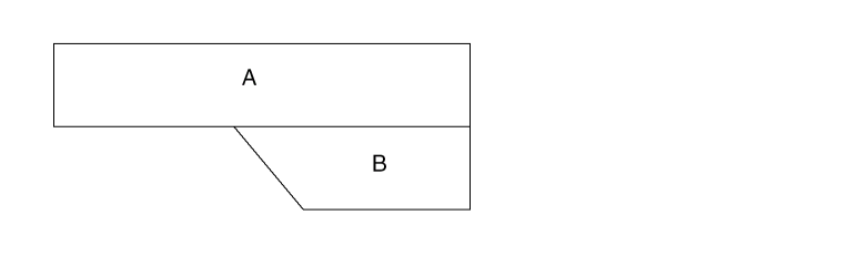
However, because of round-off effects, you might get two shapes, A and C, where C is the result of rounding off.

To prevent slivers from forming as a result of rounding off, specify the ROUND-OFF-TOLER command.
Arguments
The value of round-off tolerance allowed in dbu.
SCALE and REV-SCALE
SCALE = unit-size units
SCALEIN =unit-size unitsREV-SCALE =unit-size unitsREV-SCALEIN =unit-size units
Description
Specifies the number of internal database units that equals one layout unit. You can specify only one of these commands in the Description block. For GDSII, if you do not specify a SCALE command, the scale value defaults to the STREAM default value.
Arguments
Specifies the size of equivalent layout unit.
| CAD system | Unit referenced |
The default is the unit size of the original layout database.
Specifies units of unit-size in microns or mils. The default is the units used in the original layout database.
Examples
SCALE = .001 microns
REV-SCALE = 1000 microns
REV-SCALE = 32768 microns
REV-SCALE = 80000 microns
SCALE = .01 microns
SCALE= 0.001 mils
SCALEOUT and REV-SCALEOUT
SCALEOUT = unit-size units
REV-SCALEOUT = unit-size units
Description
Specifies the scale of the output tape (OUTDISK) when you convert a database. These commands work with the SYSOUT command. The default for SCALEOUT is SCALE. The default for REV-SCALEOUT is REV-SCALE.
When you specify different input and output file formats (that is, SYSIN does not equal SYSOUT), the conversion requires a treefile generated by a job that ran with SYSTEM and SCALE specified the same as your SYSOUT and SCALEOUT. For more information about the treefile, refer to the SYSOUT command.
Arguments
Specifies the size of equivalent layout unit.
Specifies units of unit-size in microns or mils.
SCHEMATIC
Description
For details about this command, refer to
SELECT-MODE
SELECT-MODE = LAY/SCH
Description
Indicates whether the node name or number is based on the schematic or layout in a selective LPE run. Include this command in the Description block if you want LPE to extract the layout parasitics and devices associated with a particular path.
You must use two other commands for selective LPE: LPE-QUERY and either NODE-SELECT or NODE-FILE. For details about these commands, refer to
Arguments
Specifies that LPE-QUERY use layout node names or numbers.
Specifies that LPE-QUERY use schematic node names or numbers. If you specify a schematic node name or number, LPE-QUERY reads the input schematic node names and compares them to corresponding layout node numbers to extract the parameters.
Example
SELECT-MODE = SCH
SIZE-MAX-VERTEX
SIZE-MAX-VERTEX = vertex-value
Description
Specifies the maximum number of vertices for a polygon during the rebuilding of polygons in the SIZE operation. The default number of vertices is 200, and this default is acceptable to most CAD layout systems.
Some systems can accept only 100 vertices. Others can accept up to 2,000. Use this command to change the number of vertices to obtain the maximum functionality from your system. This command does not apply to the trapezoid output layer.
Arguments
Specifies the maximum number of vertices on polygons after a SIZE operation if you specify a value less than or equal to 200. If you specify a value greater than 200, the maximum value is 2000 for the vertices. Default is 200 vertices.
Example
In this example, when building polygons from layer metal to output cell umetal52, the maximum number of vertices is 100. No OUTPUT is specified in the oversize of layer buried to trapezoid layer oburied. Therefore, SIZE-MAX-VERTEX does not apply.
*DESCRIPTION
SIZE-MAX-VERTEX = 100
.
.
*END
*OPERATION
SIZE metal BY -1 OUTPUT umetal 52
SIZE buried BY 1 oburied
*END
SIZE-MIN-WIDTH
SIZE-MIN-WIDTH = min-width-value unit
Description
Specifies the minimum width of polygon cutting by the PG handler during the rebuilding of polygons in the SIZE operation. This command does not apply to the trapezoid output-layer. For more information about sizing polygons, refer to the SIZE command in Chapter 13.
You must specify the correct minimum width value. If the value is too large, there is no place to cut the polygon. If the width of the polygon is not big enough to allow polygon cutting, the command aborts and you get an error message.
Arguments
Specifies the minimum width of polygon cutting during the rebuilding of polygons in the SIZE operation. Value range is 0.005 to 1.0 microns. Default width is 0.4 micron. This command overrides the W option in the SIZE command.
Specifies unit of MIN-WIDTH-VALUE. Micron or mil.
Example
In this example, during the building of polygons from layers cont and poly, the minimum width of polygon cutting is 0.01 microns. Because no OUTPUT is specified in the oversize of layer sink to trapezoid layer ksink, SIZE-MIN-WIDTH does not apply.
*DESCRIPTION
SIZE-MIN-WIDTH = .01 mic
...
*END
*OPERATION
SIZE cont BY 0.5 OUTPUT ocont 50
SIZE poly BY 0.2 OUTPUT opoly 51
SIZE sink BY 1 ksink
*END
The SIZE command generates the following output cells:
Output cells OCONT50A, OCONT50R, OPOLY51A, and OPOLY51R are not created if they contain no sized data.
SIZENOT
SIZENOT = cellnames
Description
Keeps alignment cells from being sized for fracturing purposes. This command is for flat mode checking only and works with LOGICAL, SIZE/GROW, and RELOCATE commands only. When used with SIZENOT, these commands must follow this sequence in the rules file:
*OPERATION
LOGICAL commands / RELOCATE commands
SIZE/GROW/SIZE commands
*END
If you use SIZENOT, you cannot use the BULK layer as the input layer for LOGICAL operations.
Arguments
Names of the alignment cells that are not to be sized.
Example
*DESCRIPTION
SIZENOT = abc def
*END
.
*OPERATION
OR L1 L2 L4
RELOCATE L1 BY -5 0 L6 MAG=5
SHRINK L2 0.5 0.7   L22
SIZE L3 BY -0.75 L33 OUT C 1
*END
SKILL-LOADER
SKILL-LOADER = user-skill-file-path
Description
If you are using Design Framework II, this command lets you use your own SKILL functions for Pcell data.
Example
SKILL-LOADER = userSkill.il
SMART-LPE
SMART-LPE = SINGLENET/PARTIAL/CRITICAL/NO
Description
Runs selective LPE and PRE. If you want to extract the layout parasitics associated with a particular net or nets in a selected window, include this command with the SINGLENET option in the DESCRIPTION block.
When PARTIAL is used, the RC for the selected nets are extracted as SINGLENET option but only extract C for the other nets. The whole result of the whole chip is output. This allows the precise timing analysis for the interested nets and has a coarse concept on the remaining nets.
When CRITICAL is used, the elements of the whole chip and the RC for the selected nets are extracted. The result of the whole chip is output.
It is strongly recommended that the command sequence in the operation block is arranged as follows to avoid unexpected results. For LPE/HLPE
Layer operations for connection and element definition
Layer operations for parasitic definition
The user-defined extraction statement
lpeselect/spfselect for output
Layer operations for connection and element definition
Element definition block (This is necessary for layout-only job, too)
Layer operations for parasitic definition
The user-defined extraction statement
Lpeselect/spfselect for output
Something that needs special attention is for a layout-only PRE/HPRE job. The element definition before the CUT-TERM command is necessary now in the new LPEQRY flow.
When Dracula runs selective LPE with SMART-LPE=SINGLENET, the source/drain of the selected loading devices can be connected to nodes that become floating in the resultant SPICE netlist. Use the FNODE-CONNECT command to connect these nodes to power or ground so that the timing analysis can be done with the SPICE output.
Arguments
Implements the selected window when used with LPE-QUERY command. It applies to LPE and PRE.
A whole circuit is output but selected nets with RC extraction and others with C extraction only.
A whole circuit is output, but only the critical nets with RC extraction.
The default. The command is ignored.
Example 1
For the following layout, if the selected net is A, only the parasitics falling into the selected-window are read in and processed. This convention improves performance.
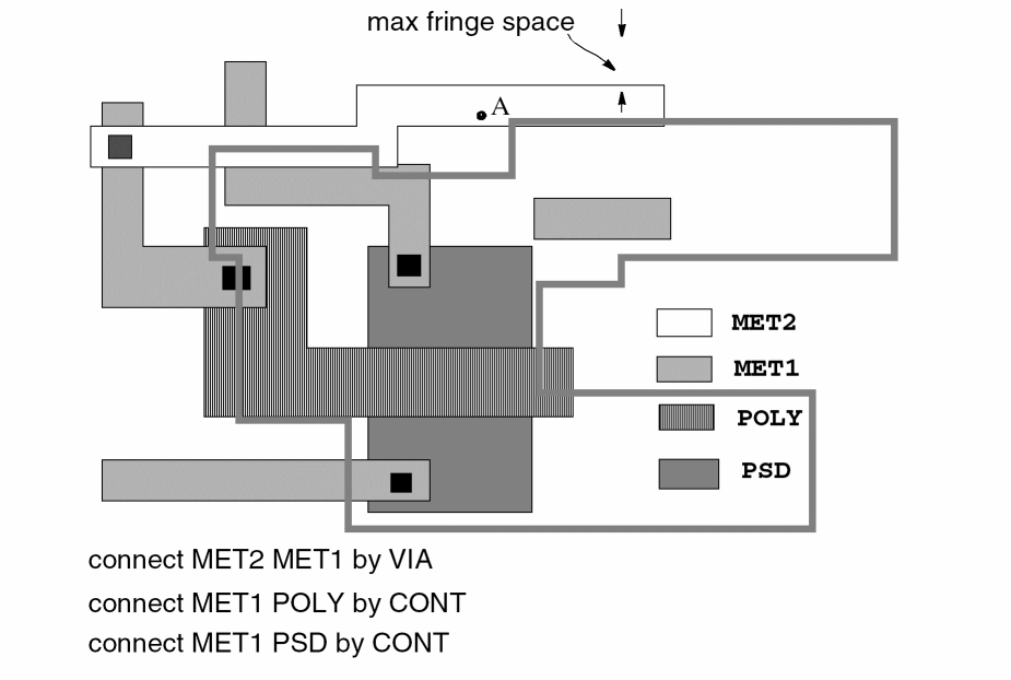
From the selected net, a selected window is formed by considering the fringe effect. Only the data in the selected window is used to extract the parasitics.
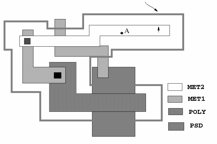
Example 2
*Desc
SMART-LPE=PARTIAL
LPE-QUERY= CORE
SELECT-MODE= LAY
*End
*Oper
...
NODE-SELECT= CK
LPESELECT[S] MOS &
LPESELECT RES &
LPESELECT CAP OUTPUT SPI
*End
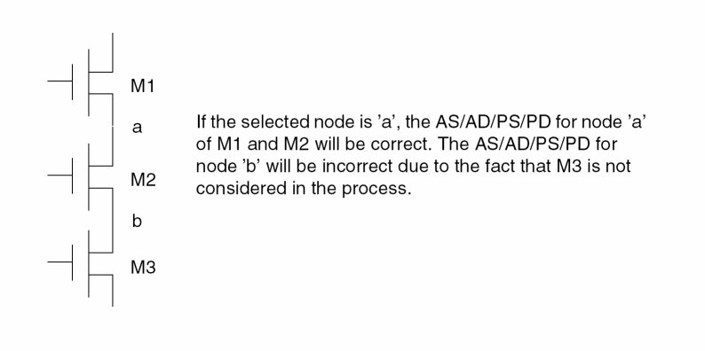
Example 3
*DESCRIPTION
SMART-LPE = CRITICAL
LPE-QUERY = ON
SELECT-MODE = SCM
*END
SMASH-CAP-TYP
SMASH-CAP-TYP = PARALLEL/SERIES/BOTH/YES/NO
Description
Smashes parallel and/or series capacitors of different subtypes, for example, CAP[N] and CAP[P].
In Dracula 4.81 and subsequent versions, the SMASH-CAP-TYP command offers new arguments that provide users with more control over smashing parallel and/or series capacitors.
Arguments
Smashes only parallel capacitors of different subtypes.
Smashes only series capacitors of different subtypes.
Smashes both parallel and series capacitors of different subtypes.
Works identical to the PARALLEL argument. Prior to Dracula 4.81, this is how the PARALLEL argument was implemented and has been retained for backward compatibility.
Does not smash parallel and/or series capacitors of different subtypes. This is the default argument.
Example
SMASH-CAP-TYP = SERIES
SMASH-FLOAT-RES
SMASH-FLOAT-RES = YES/NO
Description
Allows you to keep or smash parallel resistors with one floating terminal.
In versions prior to 4.81, Dracula will not smash these resistors. But, in Dracula 4.81 and subsequent versions, this new command lets you smash these resistors that have one floating terminal.
Arguments
Lets you smash floating resistors
Is the default and does not smash floating resistors
Example
SMASH-FLOAT-RES = YES
SMASH-MOS-TYP
SMASH-MOS-TYP = YES/NO
Description
Lets you smash parallel MOS transistors with split gates that use different device subtypes in Dracula LVS.
Previous versions of the Dracula product allowed you to only smash the split-gate serial chains of MOS transistors of the same subtype using the S option of the LVSCHK command. But, this new command, SMASH-MOS-TYP now lets you smash parallel MOS transistors with split gates that use different device subtypes. This new feature works not only for 2 pairs of transistors, but for any number. The width or length ratio of the transistors with split-gate (which have the same input) should be equal to each other.
SMASH-MOS-TYP has two optional modifiers: CARE-SPLIT-ORDER and FIX-INPUT-ORDER and you need to use SMASH-MOS-TYP with one of these modifiers.
The figure below illustrates this functionality in previous versions of the Dracula product (where only MOS transistors of the same subtype are smashed). In this example below they are all [X] models.
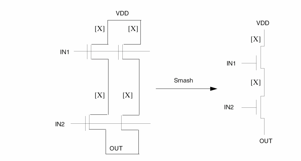
The figure below illustrates the current enhanced feature where the bottom pair of MOS transistors can use a different model, [Y] as shown here. That is, a MOS device of a different subtype gets smashed.
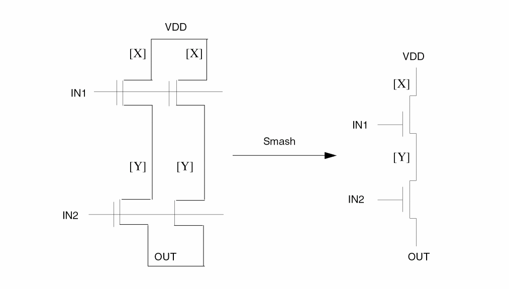
Commands Combination Matrix Table
Given below is a compatibility table for these commands. This SMASH-MOS-TYP enhancement works only with these combinations given below.
| Commands | Arguments | ||
|---|---|---|---|
PDRACULA translates this new command, SMASH-MOS-TYP for REDUCE to operate. REDUCE smashes the split-gates MOS devices with different subtype the same way as it smashes the split-gates MOS devices with the same subtypes.
PDRACULA handles the translation in three ways. PDRACULA either does the translation or issues a warning message based on whether you have
- Set the correct combinations in your rule file
- Set incorrect combinations in your rule file
- Set incomplete or conflicting rules in your rule file
Arguments
Lets you smash parallel MOS transistors with split gates that use different device subtypes.
Example
*DESCRIPTION
CARE-SPLIT-ORDER = YES
SMASH-MOS-TYP=YES
...
*END
*OPERATION
...
LVSCHK{[S]}
*END
SMASH-RES-TYP
SMASH-RES-TYP = PARALLEL/SERIES/BOTH/YES/NO
Description
Smashes parallel and/or series resistors of different subtypes, for example, RES[N] and RES[P].
In the 4.81 and subsequent versions, the SMASH-RES-TYP command provides new arguments that provide users with more control over smashing parallel and/or series resistors.
Arguments
Smashes only parallel resistors of different subtypes
Smashes only series resistors of different subtypes
Smashes both parallel and series resistors of different subtypes
Works identical to the SERIES argument. Prior to Dracula 4.81, this is how the SERIES argument was implemented and has been retained for backward compatibility.
Does not smash parallel and/or series resistors of different subtypes. This is the default argument.
Example
SMASH-RES-TYP = BOTH
SMOOTH-SIZE
SMOOTH-SIZE = EDGE45 {CIRCLE}/CIRCLE/NO
Description
Snaps all non 45-degree edges resulting from the SIZE command back to 45-degree edges. For example, if you have a big polygon in your design and a cut line intersects a 45-degree angle, the angle becomes a non 45-degree angle. To snap the angle back to 45-degrees, specify SMOOTH-SIZE = EDGE45.
For example, the following shape occurs before sizing.

After performing the following SIZE function, a non 45-degree edge results.
SIZE LAY1 BY 5 LAY2
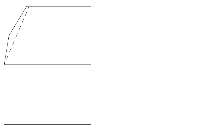
SMOOTH-SIZE = EDGE 45 snaps the edges to 45 degrees (represented by the dashed line).
If you specify SMOOTH-SIZE = CIRCLE, Dracula snaps all acute angles out to make smoother circles and curves. For example, if you enlarge and shrink a circle by a large value, the angle becomes a sharp angle (less than 10 degrees). SMOOTH-SIZE = CIRCLE snaps the angle out. This option is useful for circles or curves.
Arguments
Snaps all non 45-degree edges back to 45 degrees.
Snaps all non 45-degree edges back to 45 degrees and smooths acute angles for circles or curves.
Smooths acute angles for circles or curves.
If you specify SMOOTH-SIZE = CIRCLE, Dracula does not snap non-45 degree edges back to 45-degree edges.
Does not snap angles back to 45 degrees. Does not smooth out acute angles for circles or curves. Default.
Example
The following example snaps non 45-degree edges to 45 degrees.
SMOOTH-SIZE = EDGE45
The following example smooths acute angles.
SMOOTH-SIZE = CIRCLE
S-OPTION-CLASS
S-OPTION-CLASS = PWRGND/NONPWRGND/ALL
Description
Determines how the LVSCHK and LPECHK [S] option works. The [S] option can
- Smash MOS SUPI split gates to single SUP devices and MOS SDWI split gates to single SDW devices
- Smash any split gate devices to single PMID or SMID devices
For descriptions of these device types, refer to
Arguments
Smashes MOS SUPI split gates to single SUP devices and MOS SDWI split gates to single SDW devices. Default.
Smashes split gates that are not connected to power or ground to single PMID or SMID devices. You must also use the O option with LVSCHK or LPECHK to allow gate swapping.
Performs the PWRGND and NONPWRGND options together. Smashes all split gates, whether they are connected to power, ground, or some other text. You must also use the O option with LVSCHK or LPECHK to allow gate swapping.
Example
This example smashes all split gates not connected to power or ground to single PMID or SMID devices.
S-OPTION-CLASS = NONPWRGND
SPF-MAP-FILE
SPF-MAP-FILE = filename {NET}
Description
Specifies the SPF mapping filename for DSPF output files with the cell instance or net names in the naming convention of DFWII instead of Dracula naming convention.
Checking Methods
Arguments
Specifies the map filename output from the Cadence netlister.
If this option is turned on, then you map both instance and net names in filename for the DSPF, RSPF file. Otherwise, you only map the instance name.
Example
SPF-MAP-FILE = CDL.run1/map/current
-
DSPF without SPF-MAP-FILE for Dracula naming convention.
*|NET flags<0> 8.61E-02PF
*|P (flags<0> I 0.00E00PF 27.11 0.30)
*|I (X_Mod030636:B X_Mod030636 B I 0.00E00PF 42.90 26.10)
*|I (X_Mod051177:A X_Mod051177 A I 0.00E00PF 69.30 22.50)
*|S (flags<0>:2 68.69 6.59)
*|S (flags<0>:3 42.29 7.19)
*|S (flags<0>:6 55.50 7.19)
R54 flags<0>:2 X_Mod051177:A 2.00000E-01
R56 flags<0>:3 X_Mod030636:B 2.00000E-01
-
DSPF with SPF-MAP-FILE specified for DFII naming convention.
 *|NET flags<0> 8.61088E-02PF
 *|P (flags<0> I 0.00E00PF 27.11 0.30)
 *|I (/mod030636:B /mod030636 B I 0.00E00PF 42.90 26.10)
 *|I (/mod051177:A /mod051177 A I 0.00E00PF 69.30 22.50)
 *|S (flags<0>:2 68.69 6.59)
 *|S (flags<0>:3 42.29 7.19)
 *|S (flags<0>:6 55.50 7.19)
 R54 flags<0>:2 /mod051177:A 2.00000E-01
 R56 flags<0>:3 /mod030636:B 2.00000E-01
START-MACRO
START-MACRO =macro-name/"macro-name arg1 arg2..."
Description
Executes the specified macro before any other commands execute. You can specify only one START-MACRO command.
Arguments
The file name of the macro. Maximum file name is 128 characters.
The macro arguments. Pass macro and its arguments with opening and closing quotation marks (" ").
Examples
This example places csh abc before BEGIN: in jxrun.com.
START-MACRO = abc
This example places csh abc al a2 a3 a4 in jxrun.com, where abc is the macro and al-a4 are its arguments.
START-MACRO = "abc al a2 a3 a4"
This example compiles csh move.com /cadence/data/lvslogic.dat where move.com is a macro that contains the UNIX cp command and /cadence/data/lvslogic.dat and “.” are its arguments.
START-MACRO = "move.com /cadence/data/lvslogic.dat ."
STATUS-COMMAND
STATUS-COMMAND = "command-name"
Description
Executes a command you specify after each program module in the jxrun.com file. You can only specify one STATUS-COMMAND.
Arguments
Specifies the command or rules file name to execute after each program module. You must enclose the command and its arguments in quotation marks (" "). Maximum field is 128 characters.
Examples
These examples are for SUN/UNIX systems.
STATUS-COMMAND = "time"

STATUS-COMMAND = "time;du"
SUBCKT-NAME
SUBCKT-NAME = name
Description
Specifies the top subcircuit name in the SPICE output file produced by LPE. If you do not specify a subcircuit name, the default name is the file name in the OUTPUT portion of the LPESELECT command.
Arguments
Specifies the top subcircuit name. The name can be up to 32 characters.
Example
In this example, the program uses WABPROC as the top subcircuit name in the LPE output file SPICE.DAT. If the SUBCKT-NAME command is missing, then SPICE is the default top subcircuit name for this example.
*DESCRIPTION
     ...
SUBCKT-NAME = WABPROC
    ...
*END
*OPERATION
   ...
  LPECHK
  LPESELECT MOS &
  LPESELECT DIO &
  LPESELECT CAP GT 0 OUTPUT SPICE
*END
SUBNODE-DELIM
SUBNODE-DELIM = name
Description
Specifies the delimiter in subnode names for PRE. Subnodes are created when a node is split to introduce parasitic resistors. A subnode name is a combination of the node name or node number, the delimiter, and a subnode number. Dracula uses a netlist name if you request backannotation.
The default delimiter is a colon (:).
Checking Methods
Arguments
Specifies a delimiter of one to four characters. This delimiter must be acceptable to your version of SPICE or to CDL to run circuit simulation using PRE extraction.
Example
SUBNODE-DELIM = "###"
Input schematic node names and Dracula-created subnode numbers are concatenated with the delimiter “###”. For example, PA1 is represented as PA1###1, PA1###2, PA1###3, and so forth.
SUB-PROGRAM-NAME
SUB-PROGRAM-NAME =moduleName directory/{hotfixModuleName}
Description
Runs specific Dracula executable modules instead of the one that is normally executed by the jxrun.com file. Use this command to run hotfix modules you receive from Cadence between Dracula releases. You can have as many SUB-PROGRAM-NAME commands as needed in your command file.
Dracula also accepts the abbreviation SUB-PROG for this command.
Arguments
Specifies the name of the Dracula module that is normally called in the jxrun.com file.
Specifies the directory that contains the hotfix module.
Specifies the name of the Dracula hotfix module. If omitted, the tool defaults to the moduleName.
Example 1
If the second argument is just a directory, PDRACULA concatenates the directory with the moduleName. For example
SUB-PROGRAM-NAME = SELECT /net/nickel/usr2/tmp/
executes the SELECT module in the /net/nickel/usr2/tmp/ directory instead of the SELECT module that normally would be called by the jxrun.com file.
SUB-PROGRAM-NAME = SELECT /net/nickel/usr2/tmp/SELECT
Example 2
If the second argument is a directory combined with a hotfixModuleName, PDRACULA overrides the moduleName with the hotfixModulename from the specified directory instead of the Dracula module that is normally called by the jxrun.com file. The following example executes the module REDUCE.4.6.HOT in the /net/nickel/usr2/tmp directory instead of the REDUCE module that is called by the jxrun.com file.
SUB-PROGRAM-NAME = REDUCE /net/nickel/usr2/tmp/REDUCE.4.6.HOT
Example 3
The following example executes the module called SIZE from the directory /local/cds/IC443/tools/dracula/bin via the environment variable path_to_dracula_binaries. You have to first assign the physical location of the directory to the environment variable using the UNIX command set or setenv.
set path_to_dracula_binaries = /local/cds/IC443/tools/dracula/bin
setenv path_to_dracula_binaries /local/cds/IC443/tools/dracula/bin
The SUB-PROGRAM-NAME command starts the SIZE modules using this environment variable starting with the $ sign:
SUB-PROGRAM-NAME = SIZE $path_to_dracula_binaries/SIZE
SUBTYPE-CSENS
SUBTYPE-CSENS = YES/NO
Description
Specifies case-sensitive device subtypes for element. parasitic, and attribute definitions. If you specify SUBTYPE-CSEN = YES, devices such as MOS[N] and MOS[n] are treated as different devices. If you specify SUBTYPE-CSEN = NO, PDRACULA converts all subtypes to uppercase. If you do not use this command and you specify devices with the same subtypes with different cases, PDRACULA reports this as an error.
Arguments
Specifies case-sensitive device subtypes.
Converts all device subtypes to uppercase. Default.
Examples
*DESCRIPTION
....
SUBTYPE-CSEN = YES
....
*END
.....
*OPERATION
....
ELEMENT MOS[N] NGATE POLY NSD PWELL    ; Standard NMOS
ELEMENT MOS[n] NSGATE SPOLY SNSD PWELL ; Special NMOS
....
*END
SUMMARY-ONLY
SUMMARY-ONLY = YES/NO
Description
Specifies that the OUTDISK command is not needed, and no OUTDISK is generated from the GDS2OUT stage.
Arguments
Does not create an OUTDISK file.
Example
SUMMARY-ONLY = YES
SVS-LAYOUT
SVS-LAYOUT = schematic-file
Description
Specifies the layout data file generated by LOGLVS.
You must include this command in the Description block if you are running a schematic versus schematic (SVS) check. SVS also requires the SVS-SCHEMATIC command and, if you run hierarchical Dracula, the HCELL-COLUMN-1 command.
Arguments
Specifies the path and file name of the schematic data file generated by LOGLVS. The schematic-file directory must be different than the directory specified by the SVS-SCHEMATIC command. The default directory is the working directory.
Example
SVS-LAYOUT = /usr/cds/drac/design1
SVS-SCHEMATIC
SVS-SCHEMATIC = layout-file
Description
Specifies the schematic data file generated by LOGLVS.
You must include this command in the Description block if you are running a schematic versus schematic (SVS) check. SVS also requires the SVS-LAYOUT command and, if you run hierarchical Dracula, the HCELL-COLUMN-1 command.
Arguments
Specifies the path and file name of the layout data file generated by LOGLVS. The layout-file directory must be different than the directory specified by the SVS-LAYOUT command. The directory cannot be the working directory.
Example
SVS-SCHEMATIC = /usr/cds/drac/layout1
SYSOUT
SYSOUT = format {treefile}
Description
Specifies the CAD-system format of the output tape (OUTDISK) if you want a format different from the one you specified in the SYSTEM or SYSIN command. For example, if SYSTEM = GDS2 and SYSOUT = CADENCE, the input is a GDSII database and the output error file is in CADENCE format.
This command requires a treefile generated by a Dracula job that ran with the format you want. This treefile contains information on the scale and physical unit of the format. If none is specified, it will default to using the treefile previously created by the Dracula job.
Arguments
Outputs in one of the following formats:
In this format, PDRACULA performs an additional SIZE stage to convert trapezoid files to polygon files. A new module called GENANO outputs net attribute(23) (layout net names for connection layers and contact layers), and device attribute(17) (layout device names in output polygon files). The names must match the names that are output in the HSPICE file.
GDS2OUT merges all of the output cell data from SIZE and forms a flat database. Except for connectivity, any text attached to the layout database or coming from an external file is output in annotated GDSII as well.
Cadence Design Framework II SKILL format
Cadence Design Framework II 4.4DD SKILL format
Specifies the treefile name from a previous run that specified SYSTEM and SCALE the same as you now specify SYSOUT and SCALEOUT (maximum eight characters, with the default extension .DAT assumed). If none is specified, it will default to using the treefile created by Dracula job.
Cadence Design Framework II SKILL format.
SYSTEM or SYSIN
SYSTEM/SYSIN = format
Description
Specifies your CAD system and the format of your input and output graphic file. You must specify this command in the Description block.
For information about CAD-system database records supported, refer to Appendix A, “Supported Database Records.”
Arguments
Specifies one of the following CAD system formats:
Design Framework II database, CDSIN44
Examples
SYSTEM = GDS2
SYSTEM = OA22
- - - -
SYSIN = GDS2
SYSIN = OA22
- - - -
TEXT-HEIGHT
TEXT-HEIGHT = size {units}
Description
Specifies height for text in OA22 database. Used only when SYSOUT (or SYSTEM) is OA22.
Arguments
Text height in MIL or MIC. If size is not divisible by resolution it is rounded. If size is smaller then 6 DBU, a warning is issued. If TEXT-HEIGHT is not set, default value of size 1.0 used.
Specifies the units of size. Must match units in SCALE and RESOLUTION (microns or mils).
Examples
TEXT-HEIGHT=100
TEXT-LEVEL
TEXT-LEVEL = n1:n2 / n
Description
Specifies the number of levels of hierarchy from which to read text. This command applies to cell and composite texts. Count the depth levels from the primary cell or level 0.
Arguments
The range of levels of hierarchy from which Dracula reads text.
The range from 0 to n levels of hierarchy from which Dracula reads text.
Examples
In this example, Dracula reads text from the primary cell.
TEXT-LEVEL = 0
In this example, Dracula reads text from level 0 to level 3.
TEXT-LEVEL = 3
In this example, Dracula reads text from level 3 to level 5.
TEXT-LEVEL = 3:5
In this example, Dracula reads text from level 3 only.
TEXT-LEVEL = 3:3
TEXT-PRI-ONLY
TEXT-PRI-ONLY = YES/NO
Description
Processes only the text associated with the top-level (primary) cell in the layout. This command ignores text associated with cells nested below the top-level cell, even if the text is on the same text layer number. If you do not specify TEXT-PRI-ONLY, Dracula places all text at the top level and processes it.
Arguments
Processes text associated with the top-level cell only.
Processes all text from all cells. Default.
Example
This example processes only text associated with the top level and uses the primary cell structure chip.
TEXT-PRI-ONLY = yes
PRIMARY = chip
TNAMES-CSEN
TNAMES-CSEN = YES/NO
Description
Specifies text name case sensitivity for all commands that contain text names. These include, but are not limited to, POWER-NODE, GROUND-NODE, PULL-UP, PULL-DOWN, PROBE, SELECT LABEL, LCONNECT, and ECONNECT.
This command affects all text names you specify in the layout and in EDTEXT or HEDTEXT files.
To specify both text name and cell name case sensitivity, you must also specify the CNAMES-CSEN command.
Arguments
Passes the exact name and character cases from the text files to the jxrun.com file.
Converts all text names to uppercase.
If TNAMES-CSEN = YES and CNAMES-CSEN = NO, Dracula converts cell names to uppercase and passes the exact text names to the jxrun.com file.
If TNAMES-CSEN = YES and CNAMES-CSEN = YES, Dracula passes the exact name and character cases from the commands and text file to the jxrun.com file.
If TNAMES-CSEN = NO and CNAMES-CSEN = YES, Dracula passes the exact name and character cases from the commands to the jxrun.com file and converts the text names to uppercase.
If TNAMES-CSEN = NO and CNAMES-CSEN = NO, Dracula converts all cell and text names to uppercase.
TRANSISTOR
TRANSISITOR = number
Description
Pre-allocates more swap space at the start of every Dracula module depending on the expected number of transistors in the layout. This command is the counterpart to the TRANSISTOR command for LOGLVS.
If you are running a very large job and more swap space is needed during execution of a module, that module must stop, request more swap space from the system, and execute from the beginning again. If you allocate enough additional swap space the first time, the above procedure repeats itself until sufficient swap space is allocated to complete the module. Therefore, the TRANSISTOR command saves valuable time.
Arguments
Specifies the number of transistors you expect in the layout. Default is 100,000.
Example
TRANSISTOR = 2000000
UNIT
UNIT = (parameter-name,parameter-unit...)
Description
Associates natural units to parameters extracted by LPE. These unit names appear in the SPICE-format listing generated by LPE. If you do not specify the unit name, Dracula reports only the parameter. You can repeat this command as needed.
Arguments
Specifies the parameter. Use only the following names:
CAPACITANCE
AREA
PERIMETER
RESISTANCE
Specifies the unit name of the parameter used in the circuit simulation.
PF = P = 1E-12
F = 1E-15
N = 1E-9
U = 1E-6
M = 1E-3
K = IE3
Example
UNIT = CAPACITANCE,PF AREA,P PERIMETER,U RESISTANCE, K
UNSPEC-LAY-PARA
UNSPEC-LAY-PARA = YES/NO/EXCEPT-SUBSTRATE
Description
Reports unspecified layout parameters of matched devices in the LVS report file. Dracula considers the unspecified parameters of matched devices as errors and reports them as a mismatch. LVS does not compare the parameters between the devices if the parameter was not specified in the netlist or layout.
Dracula reports the total number of unspecified parameters in the .lvs summary file. The UNSPEC-LAY-PARA command reports these discrepancies with each device. Use the EXCEPT-SUBSTRATE command if you do not want Dracula to report unspecified substrates.
Arguments
Considers an unspecified parameter as an error and reports the error as UNKNOWN. You can identify the devices that do not have their layout parameters specified.
Suppresses unspecified SUBSTRATE warnings.
UNSPEC-PARA
UNSPEC-PARA = YES/NO/EXCEPT-SUBSTRATE
Description
Reports unspecified parameters of matched devices in the LVS report file. Dracula LVS considers the unspecified parameters of matched devices as errors and reports them as a mismatch. LVS does not compare the parameters between the devices if the parameter was not specified in the netlist or layout.
Dracula reports the total number of unspecified parameters in the .lvs summary file. The UNSPEC-PARA command reports these discrepancies with each device. Use the EXCEPT-SUBSTRATE command if you do not want Dracula to report unspecified substrates.
Arguments
Considers an unspecified parameter as an error and reports the error as UNKNOWN. You can identify the devices that do not have layout or schematic parameters specified.
Suppresses unspecified SUBSTRATE warnings.
Sample Report
This sample report shows how the .lvs report appears with UNSPEC-PARA warnings.
UNSPEC-SCH-PARA
UNSPEC-SCH-PARA = YES/NO/EXCEPT-SUBSTRATE
Description
Reports unspecified schematic parameters of matched devices in the LVS report file. Tells Dracula to consider the unspecified parameters of matched devices as errors and reports them as a mismatch in the LVS report file. LVS does not compare the parameters between the devices if the parameter was not specified in the netlist or schematic.
Dracula reports the total number of unspecified parameters in the .lvs summary file. The UNSPEC-SCH-PARA command reports these discrepancies with each device. Use the EXCEPT-SUBSTRATE command if you do not want Dracula to report unspecified substrates.
Arguments
Considers an unspecified parameter as an error and reports the error as UNKNOWN. You can identify the devices that do not have their schematic parameters specified.
Suppresses unspecified SUBSTRATE warnings.
WINDEL
WINDEL = xmin ymin xmax ymax
Description
Deletes an area within a window from processing to conserve system resources. For CHECK-MODE = FLAT or HIER, Dracula keeps data that lies across the WINDEL coordinate lines until it encounters the next trapezoidal cut line inside the WINDEL area unless you also specify
WINDOW-CUT=EDGE.
When checking using CELL or COMP, the layout that lies across WINDEL coordinate lines is cut. Only the portions outside the WINDEL coordinate lines are kept. This separation occurs unless you specify WINDOW-CUT = TRAPEZOID in your run file.
You can specify up to 50 WINDEL areas.
WINDEL with Hierarchical Dracula
The WINDEL command works only on the composite plane in hierarchical or composite mode. WINDEL is ignored in cell mode and on the cell plane of hierarchical or composite mode.
Arguments
Specifies the minimum x coordinate of window to delete from processing.
Specifies the minimum y coordinate of window to delete from processing.
Specifies the maximum x coordinate of window to delete from processing.
Specifies the maximum y coordinate of window to delete from processing.
Example
PRIMARY = iomux
WINDOW = 50. 50. 220. 220.
WINDEL = 150. 80. 190. 180.
WINDEL = 70. 150. 130. 200.
WINDOW
WINDOW = xmin ymin xmax ymax
Description
Specifies a window to process. For CHECK-MODE = FLAT or HIER, Dracula keeps data that lies across WINDOW coordinate lines until it encounters the next trapezoidal cutline outside the WINDOW area unless you specify WINDOW-CUT = EDGE in your run file.
When checking using CHECK-MODE = CELL or COMP, the layout that lies across window coordinate lines is cut. Only the portions inside the window coordinates are kept. This separation occurs unless you also specify WINDOW-CUT = TRAPEZOID in your run file.
You can specify multiple window areas (maximum of 50). The default for WINDOW is the entire primary cell. Dracula issues the following fatal error message if you specify a window outside the substrate layer:
*/FE*** FATAL ERROR DETECTED: NO DATA HAVE BEEN FOUND
-- PLEASE CHECK DATABASE AND WINDOW SIZES.
WINDOW with Hierarchical Dracula
The WINDOW command works on the composite plane in hierarchical or composite mode only. Dracula ignores WINDOW in cell mode and on the cell plane of hierarchical or composite mode.
Arguments
Specifies the minimum x coordinate of window to process.
Specifies the minimum y coordinate of window to process.
Specifies the maximum x coordinate of window to process.
Specifies the maximum y coordinate of window to process.
Example
PRIMARY =iomux
WINDOW  =50. 50. 220. 220.
WINDOW  =220. 220. 400. 400.
WINDOW  =800. 800. 1000. 1000.
WINDOW-CUT
WINDOW-CUT = TRAPEZOID/EDGE
Description
Keeps or cuts the portion of a trapezoid that falls across the coordinates specified in a WINDOW, WINDEL, or HCELL command with the FRAME BY option.
Arguments
Keeps the trapezoid if it falls across the window boundary. This is the default for flat and hierarchical mode.
Cuts the trapezoid along the window edge and keeps the portion that fulfills the criteria (that is, the portion inside the window if you specified the WINDOW command or the portion outside the window if you specified the WINDEL command, or HCELL with FRAME BY option). Default for cell and composite modes.
WORK-DIR
WORK-DIR = directory-name
Description
Specifies the run directory. Dracula places all files generated by the job in this directory or subdirectory. You must enter the full name when you specify this command.
In Dracula 4.81 and subsequent versions, PDRACULA now adds the current directory to the INDISK and/or OUTDISK name if you set the following:
- Specify the WORK-DIR directory
-
Leave INDISK and/or OUTDISK as just a file name (without a forward slash (that is, / )In this release and subsequent releases, you must specify the WORK-DIR command before the “Input-Layer Block” section of your Dracula rules file.
If you specify the WORK-DIR command after the “Input-Layer Block” section of your Dracula rules file, PDRACULA issues a warning message similar to this example below:** ERROR : WORK-DIR SHOULD BE SPECIFIED BEFORE *INPUT-LAYER SECTION
THE ERROR MESSAGE LISTED ABOVE IS FOR THE FOLLOWING CARD:
WORK-DIR = ./work1/
Arguments
Specifies the directory name or an assigned logical name. The default is your current directory. The maximum command line length is 128 characters.
Example
WORK-DIR = DBAO:[TEST.DRC]
WORK-DIR = DBA1:[PROD]
You cannot run more than one job at a time from your current or default directory even if you use different work directories. Even though Dracula runs in the working directory, it is run from files in your default directory. Those files can only run one job at a time.
The following files are either required by or generated in the default directory and a working directory. The working directory contains the INDISK, OUTDISK, and EDTEXT files unless you specify path names.
| Default directory | WORK-DIR directory |
|---|---|
System Info
| System name | Modify the command |
|---|---|
ZERO-SPAC-F-EQU
ZERO-SPAC-F-EQU = YES/NO
Description
Used to calculate zero and nonzero spacing capacitance with an equation. The program displays a warning message if "divided by 0" is found in the equation.
Arguments
Turns on the function as described above.
This is the default and will be ignored.
Example 1
Both the zero and nonzero spacing fringe capacitance is calculated with the following equation.
*DESCRIPTION
...
ZERO-SPAC-F-EQU =YES
*END
*OPERATION
FRINGE CAP[A] ME1 ME2
ATTRIBUTE CAP[A] 0 1
ATTRIBUTE CAP[A] .5 1
LEXTRACT CAPF ME1 ME2 BY CAP[A] LCAPA &
EQUATION C = WIDT / SQRT((((3.205 + DEPT)**2.861/6.259)**2) + 57.5)
*END
Example 2
Without this command, Dracula uses C=K*WIDT as the equation for zero spacing fringe capacitance and the following equation
C = WIDT / SQRT((((3.205 + DEPT)**2.861/6.259)**2) + 57.5)
for nonzero spacing fringe capacitance.
*OPERATION
FRINGE CAP[A] ME1 ME2
ATTRIBUTE CAP[A] 0 1
ATTRIBUTE CAP[A] .5 1
LEXTRACT CAPF ME1 ME2 BY CAP[A] LCAPA &
EQUATION C = WIDT / SQRT((((3.205 + DEPT)**2.861/6.259)**2) + 57.5)
*END
Return to top