5
Editing Fluid Guard Rings
The new generation FGRs comprise fluid shapes. You can perform level-1 editing on these FGR instances.
To use the Stretch, Quick Align, Reshape, and Split commands, ensure that the Fluid Shape option is selected in the Objects assistant. The Fluid Shape option controls the selectability of the fluid shapes in FGRs for level-1 editing. If the Stretch, Quick Align, Reshape, or Split command is running and the Fluid Shape option is selected in the Objects assistant, the fluid shape can be selected and it highlights dynamically. If, however, the Fluid Shape option is not selected, the fluid shape cannot be selected; instead, the entire FGR instance is selected.
In addition, you can use the commands on Edit – Fluid Pcell menu for editing FGRs. By using these commands, you can perform the following edit operations on FGRs:
- Stretching a Fluid Guard Ring
- Aligning a Fluid Guard Ring
- Reshaping a Fluid Guard Ring
- Splitting a Fluid Guard Ring
- Chopping a Fluid Guard Ring
- Merging Fluid Guard Rings
- Converting a Fluid Guard Ring to a Polygon
- Creating a Tunnel Through a Fluid Guard Ring
- Healing a Fluid Guard Ring
-
Cleaning Overlapped Contacts from Fluid Guard Rings
Stretching a Fluid Guard Ring
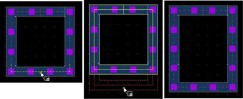
The FGR instances created using Wrap Tab, Path Tab, or Rect Tab modes result in guard rings with fluid shapes of the type path. You can stretch such fluid guard rings by using the center line or the vertex of the path.
Stretching Path Type Fluid Shapes
You can stretch a path-based FGR in the same way you stretch a path object at level 0. For more information about stretching and how it is done, refer to the Stretching Objects section in the
You cannot stretch a path-based FGR along its edges because the width of a path cannot be variable along its length. To stretch a path-based FGR along the boundary edges to increase the number of contacts, first convert the path-based FGR to a polygon. For more information, see Converting a Fluid Guard Ring to a Polygon.
While stretching a rectangular FGR that has any of the edges connected to another FGR, select the Keep Guard Ring Ends Connected check box in the Stretch form. This enables you to stretch the rectangular guard ring from all corners. For detailed information about the fields on this form, refer to the Stretch Form section.
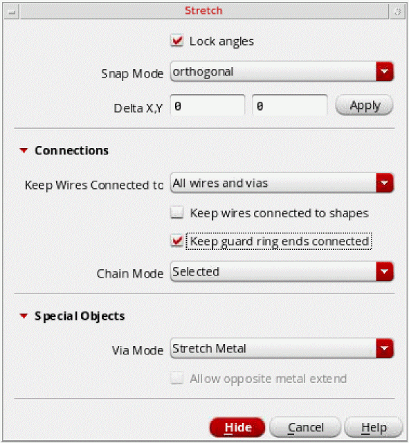
The Stretch command supports both pre-selection and post-selection of guard rings.
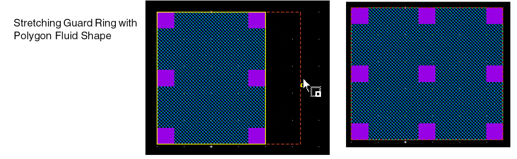
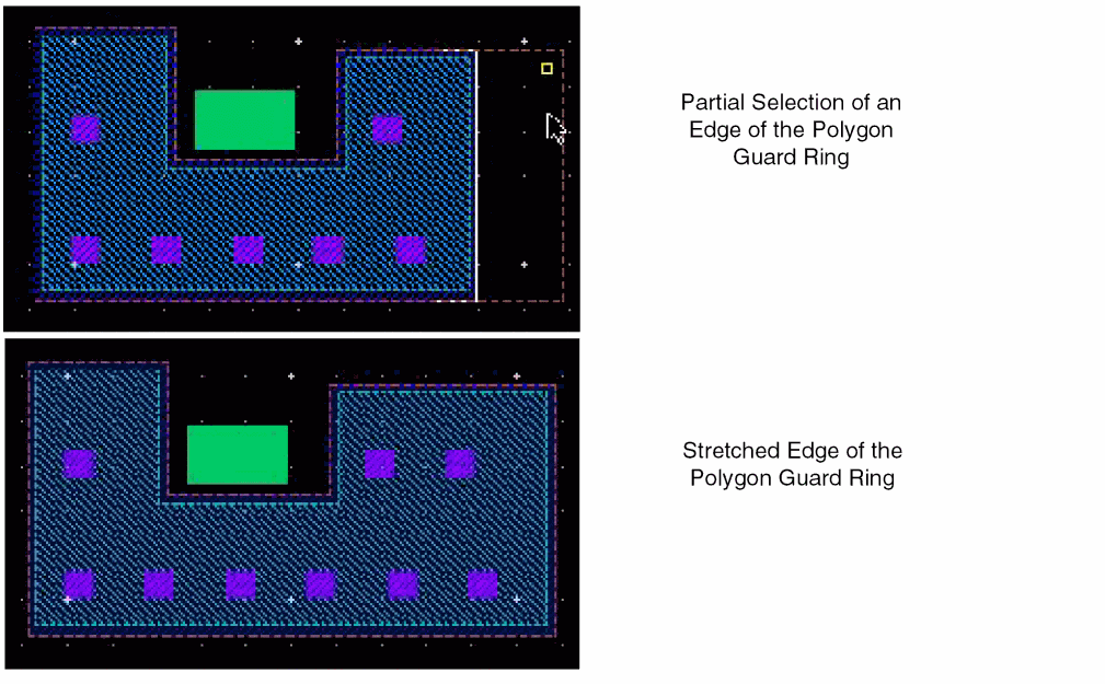
Stretching Polygon Type Fluid Shapes
You can stretch the edge of only those guard rings whose fluid shape is of the type polygon. While stretching the edge of such a guard ring, only the fluid shape is stretched. Individual shapes of a guard ring can neither be selected nor be stretched. You can stretch a guard ring with path/pathSeg fluid shape by stretching the centerline.
You can stretch a guard ring to modify:
-
The size of a guard ring by using the path or pathSeg centerline stretch
-
The width of one side of a polygon guard ring or after converting the path or pathSeg guard ring to a polygon

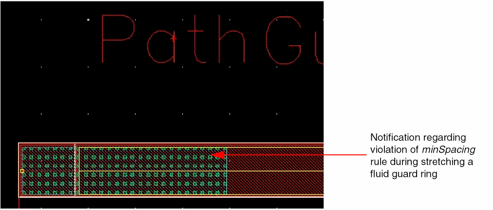
Design-rule-driven (DRD) rules are also supported during the FGR editing process (Stretch command). You can enable the Enforce, Notify, or Post Edit mode at the current to bottom hierarchy depth while editing an FGR. You can specify the DRD rules that need to apply through the DRD Options form accessed from the DRD toolbar or the Options — DRD Edit menu. For more information, see Creating Fluid Guard Rings (Old GUI).
Aligning a Fluid Guard Ring
You can align only the fluid shape of a guard ring by using the Edit – Quick Align command. The fluid shape should be of the type path or polygon. In addition to aligning FGRs, you can use the smart snapping and target edge highlighting features of the Quick Align command to stretch the fluid shape of a guard ring to a target object. Individual shapes of a guard ring cannot be selected or aligned.
For more information about aligning and how it is done, refer to the following sections in the Virtuoso Layout Suite L User Guide:
- Aligning Objects section in the Editing Objects chapter
- Quick Align Form section in the Layout L Forms appendix
Reshaping a Fluid Guard Ring
You can reshape only the fluid shape of a guard ring. The Reshape command alters the fluid shape points and re-generates the underlying guard ring based on the new points. Individual shapes of a guard ring can neither be selected nor be reshaped.
Reshaping a guard ring that is created from a path or polygon fluid shape is similar to reshaping an equivalent shape (path or polygon) in the design. For more information about reshaping and how it is done, refer to the
The pointer snapping follows the Gravity Controls settings in the Layout Editor Options Form. If Gravity On is selected and Depth is greater than 0, the pointer snaps to objects in the vicinity of the pointer based on the Types selected and the specified Aperture value. If Gravity On is not selected, smart snapping is the default pointer snapping mode. The pointer snaps to the highlighted edge when you click.
To reshape a guard ring with a path or pathSeg fluid shape:
- Choose Edit – Advanced – Reshape or click the Reshape icon on the Guardring toolbar.
-
Select the guard ring you want to reshape.
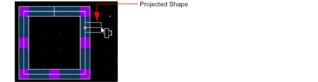
If you move the pointer within the Aperture distance (set in the Layout Editor Options Form) from the selected shape and click, a projected shape appears from the centerline of the path or pathSeg, as shown below.
-
Click to start the reshape from the required starting point.
The projected shape anchors to the guard ring at the click point. -
Click to define the new points of the reshaped figure, as shown below.
While defining the new points of the reshaped figure, if you bring the pointer within Aperture distance from the selected shape, the projected shape appears. You can choose to finish the reshaping here by pressing the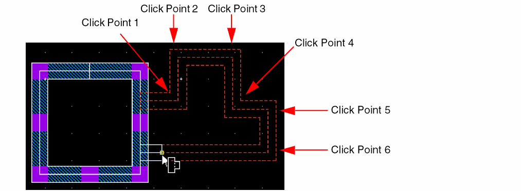
Spacebarkey or continue to click to define more points of the reshaped figure. -
Click to add the highlighted shape to the original selected shape.
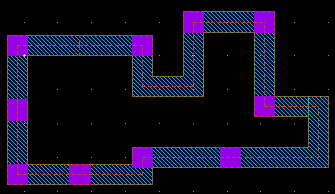
The original guard ring is reshaped based on the specified new points.
To reshape a guard ring with a polygon fluid shape:
- Choose Edit – Advanced – Reshape or click the Reshape icon on the Guardring toolbar.
-
Select the guard ring you want to reshape.
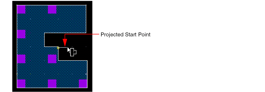
If you move the pointer within the Aperture distance (set in the Layout Editor Options Form) from the selected shape, a projected start point appears from the edge of the polygon fluid shape, as shown below.
-
Click to start the reshape from the projected start point.
If required, you can pressF3and change the Snap Mode in the Reshape Form. -
Click to define the new points of the reshaped figure, as shown below.
While defining the new points of the reshaped figure, if you bring the pointer within Aperture distance from the selected shape, the projected end point appears. You can choose to finish the reshaping here by pressing the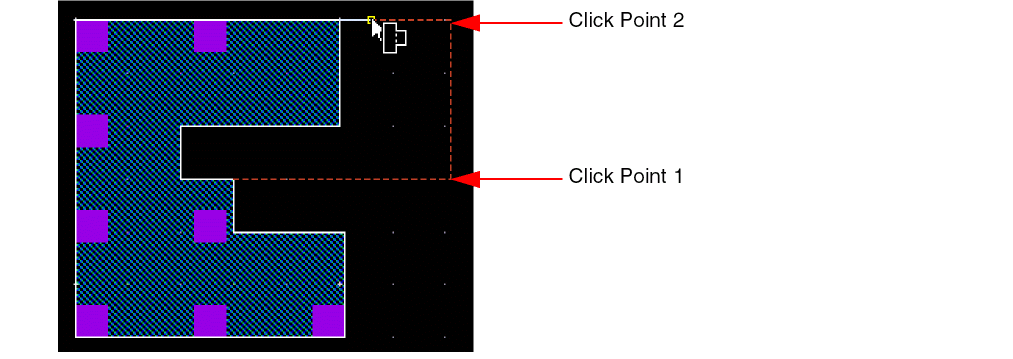
Spacebarkey or continue to click to define more points of the reshaped figure. -
Press the
Spacebarkey when the projected end point is visible.
This enables the smart snapping mode. - Click to add the highlighted shape to the original selected shape.
- Click the middle-mouse button to toggle between the versions of the possible reshaped figures.
-
Click to select the highlighted version.
The original guard ring is reshaped based on the specified new points.
Splitting a Fluid Guard Ring
You can split only the fluid shape of an FGR. The fluid shape can be of the type path or polygon. The Split command alters the fluid shape points and re-generates the underlying guard ring based on the new points. Individual shapes of a guard ring can neither be selected nor be split.
Splitting a guard ring that comprises a path or polygon fluid shape is similar to splitting an equivalent shape (path, rectangle, or polygon) in the design.
The steps to split the fluid shape of an FGR are the same from step 3 onwards described in the Ctrl+s], and if you want, open the Split form by pressing F3. Then, select the fluid shape of the FGR, and not the complete FGR instance.
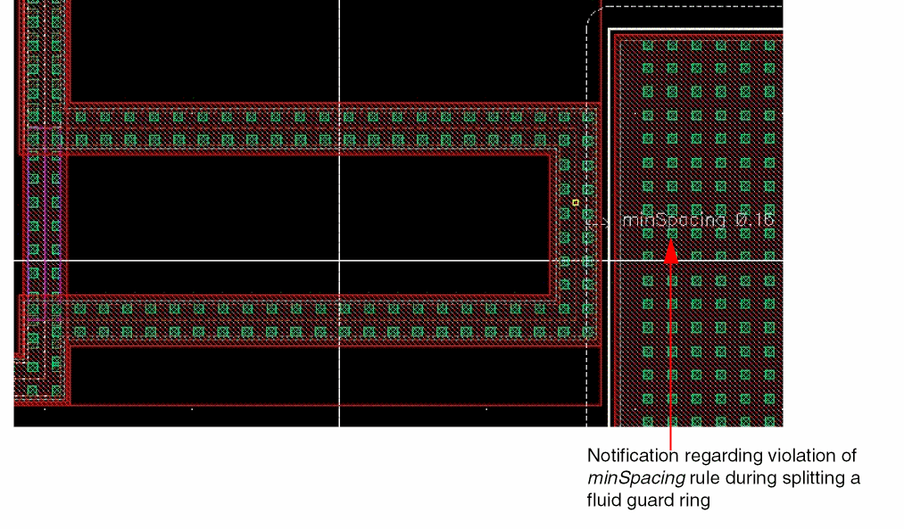
The Split command also supports the DRD rules, as illustrated below.
Chopping a Fluid Guard Ring
The Edit – Fluid Pcell – Chop command enables you to remove a part of an FGR or cut it into pieces. You can chop a guard ring in both pre-select and post-select modes and even when no object is selected. The Chop command cuts across all the layers of the FGR device. If the result of chopping an FGR divides it into multiple distinct parts, then a new FGR device gets created corresponding to each of the respective parts. The Chop command automatically converts an FGR to a polygon.
This section covers the following:
- Types of Chop Shapes
- Chopping a Fluid Guard Ring Without Selecting It
- Pre-Selecting a Fluid Guard Ring to be Chopped
- Post-Selecting a Fluid Guard Ring to be Chopped
Types of Chop Shapes
The Chop Fluid Objects Form displayed using the Edit – Fluid Pcell – Chop menu enables you to use the following types of shapes to chop a fluid guard ring:
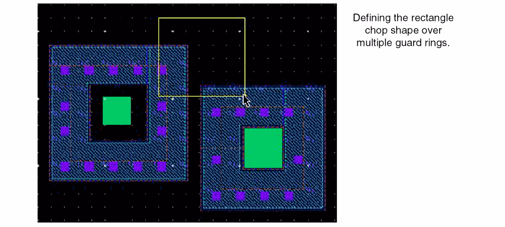
Using Rectangle as the Chop Shape
When you select rectangle mode on the Chop Fluid Object form, do the following:
- Click to define the opposite corners of the chop rectangle that intersects the guard ring in the region that needs to be chopped.
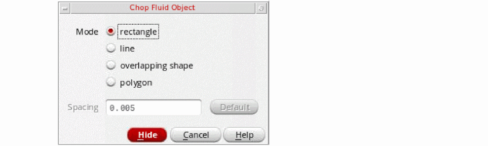
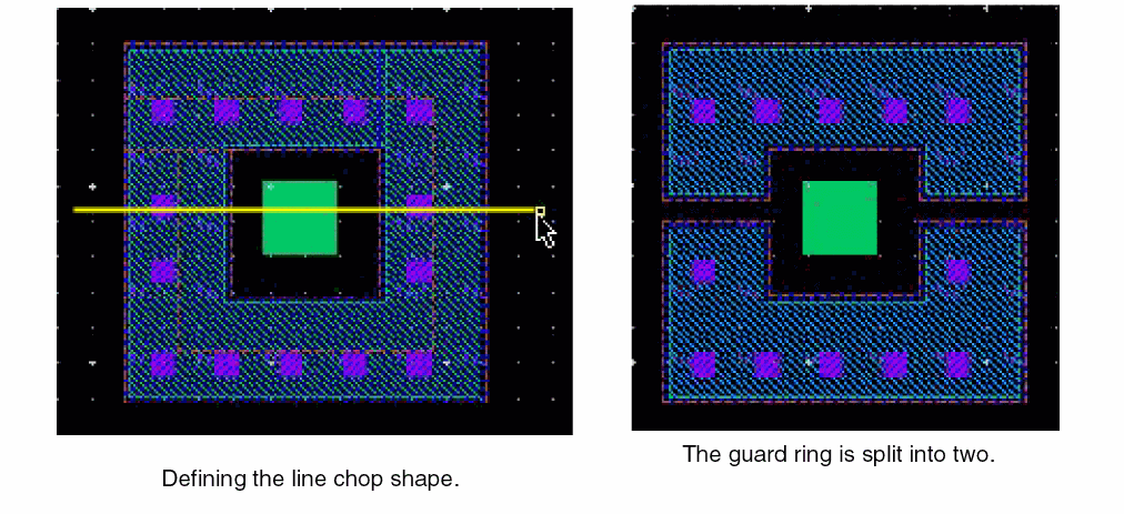
Using Line as the Chop Shape
When you select line mode on the Chop Fluid Object form, do the following:
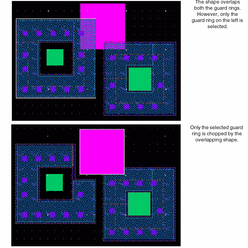
Using Overlapping Shape as the Chop Shape
When you select overlapping shape mode on the Chop Fluid Object form, do the following:
Using Polygon as the Chop Shape
When you select to polygon mode on the Chop Fluid Object form, do the following:
-
Click to define the points of the chop polygon that intersects the guard ring in the region that needs to be chopped.
Chopping a Fluid Guard Ring Without Selecting It
To chop a guard ring without selecting it first:
- Choose Edit – Fluid Pcell – Chop.
-
Press
F3.
The Chop Fluid Objects Form appears. - Select a Mode and update the Spacing value as required, if applicable.
-
Create the chop shape to intersect the guard ring or click the shape overlapping the guard ring.
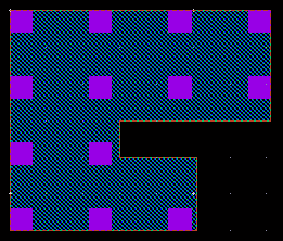
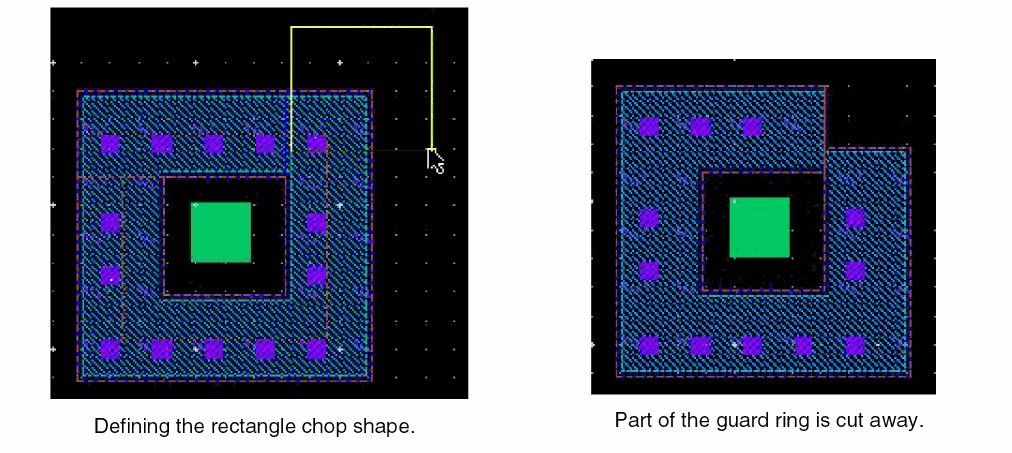
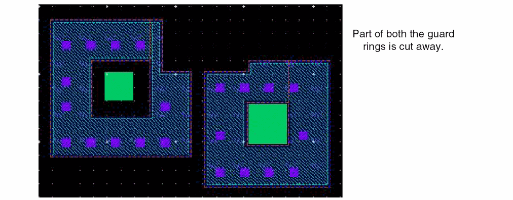
All the guard rings that are intersected by the chop points are either split or a part is cut away. This is illustrated in the figures below.
 If a shape overlaps multiple guard rings and no guard ring is selected, all the guard rings are chopped if overlapping shape is the selected Mode.
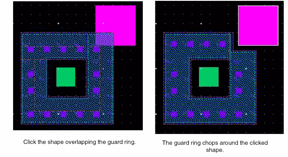
-
Press
Escor click Cancel in the form to complete chopping guard rings.
Pre-Selecting a Fluid Guard Ring to be Chopped
If the chop shape is drawn such that it intersects multiple guard rings, only the pre-selected guard ring gets chopped.
To chop a selected guard ring:
- Select the guard ring you want to chop.
- Choose Edit – Fluid Pcell – Chop.
-
Press
F3.
The Chop Fluid Objects Form appears. - Select a Mode and update the Spacing value as required, if applicable.
-
Create the chop shape to intersect the selected guard ring or click the shape overlapping the selected guard ring.
The selected guard ring is either split or a part of the guard ring is cut away. This is illustrated in the figures below.
When overlapping shape is the selected Mode and a shape overlaps multiple guard rings, only the selected guard ring is chopped. This is shown in the figure below.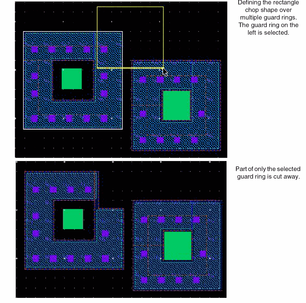
-
Press
Escor click Cancel in the form to complete chopping guard rings.
Post-Selecting a Fluid Guard Ring to be Chopped
To chop a post-selected guard ring:
- Choose Edit – Fluid Pcell – Chop.
-
Press
F3.
The Chop Fluid Objects Form appears. - Select a Mode and update the Spacing value as required, if applicable.
-
Select a guard ring either by pressing
Shiftand clicking the guard ring or by pressingShiftand area selecting the guard ring. You can add more guard rings to the selection by using either key combination. -
Create the chop shape to intersect the selected guard ring or click the shape overlapping the selected guard ring.
The selected guard ring is either split or a part of the guard ring is cut away. -
Press
Escor click Cancel in the form to complete chopping guard rings.
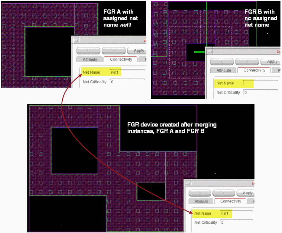
Merging Fluid Guard Rings
When you merge certain FGRs, a new FGR device gets created. The FGRs to be merged should meet the following criteria:
- The FGRs must be overlapping.
- The FGRs belong to the same device class.
- The FGRs belong to the same net or only one of the FGRs is associated with a net.
A merged FGR device has the following noteable characteristics:
- Any tunnels in the original FGRs are retained in the merged FGR as well. For more information about creating tunnels, see Creating a Tunnel Through a Fluid Guard Ring.
- Any existing labels get removed from the instance because the merge operation leads to creation of a new instance.
-
Net name assigned to an FGR instance is inherited by the merged FGR device, if one of the FGR instance has net name.
The net name can be defined at the time of creation in the Create Guard Ring form using one of the following methods:- The Net Name field on all tabs.
- The Net Name field on the Outer Rings subtab of the Wrap and Rect tabs.
Otherwise, you can define the Net Name on the Connectivity tab of the Edit Instance Properties form while editing an FGR instance.
For example, if instance FGR A having net name net1 assigned to it is merged with another instance FGR B that does not have a net name, the merged FGR device inherits the net name of the first instance as shown in the figure below.
FGR instances can be merged in pre-select and post-select modes as explained in the following sections:
For information about the inheritance of parameters in the merged instances, see Merging Fluid Guard Rings with Unmatched Parameters.
Pre-Selecting Fluid Guard Rings to be Merged
-
Select the overlapping FGRs you want to merge.
-
Choose Edit – Fluid Pcell – Merge.
The selected FGRs are merged.
-
Press
Escto finish merging guard rings.
Post-Selecting Fluid Guard Rings to be Merged
To merge post-selected overlapping FGRs:
- Choose Edit – Fluid Pcell – Merge.
- Click the first guard ring.
-
Click the next guard ring that is overlapping the first one.
The two guard rings are merged. -
If required, continue to select any more overlapping FGRs.
All the overlapping guard rings are merged if they meet the merge criteria.
Alternatively, after starting the Merge command, you can also area select the entire or part of a design containing guard rings. Then, click anywhere in the design or pressEnterto run the Merge command. All the selected, overlapping guard rings that satisfy the merge criteria are merged. -
Press
Escto finish merging guard rings.
Merging Fluid Guard Rings with Unmatched Parameters
While merging FGR instances with unmatched parameters, the merge command uses one FGR instance as the master.
While identifying which FGR instance should be considered as the master, Virtuoso considers the one that is nearest to the origin. All parameters on the merged FGR instances are inherited from that of the master FGR instance. This can be understood from the following figure:
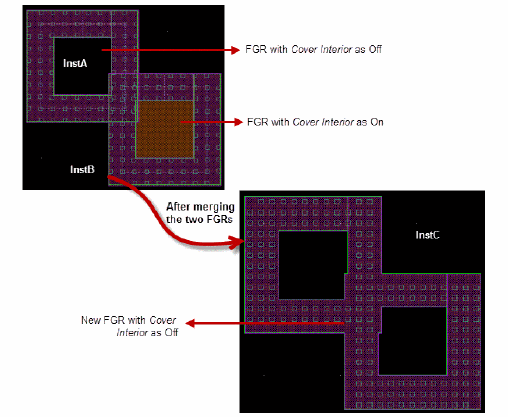
In this figure, instA and instB have been merged to create instC. The settings of the Cover Interior parameter for instC has been inherited from instA, which had this parameter set to off. This is because the origin of instA is before instB.
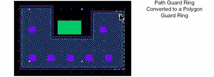
Converting a Fluid Guard Ring to a Polygon
The Convert to Polygon command is useful for converting a path-based guard ring to a polygon guard ring. A path cannot have different widths along its length. You can convert a path-based guard ring to a polygon to achieve the desired editing results on the guard ring. Examples of such editing, which cannot be achieved with a path-based guard ring, include:
- Stretching a guard ring such that the number of contact rows is different along the various edges of the guard ring
- Reshaping part of a guard ring edge so that it has a different width
You can run the Convert to Polygon command in both pre-select and post-select modes.
To convert a path guard ring to a polygon:
-
Select the path guard ring.
-
Choose Edit – Fluid Pcell – Convert to Polygon.
The path guard ring is converted to a polygon guard ring.
-
Press
Escto finish converting path guard rings to polygon guard rings.
You can now stretch or reshape the edges of the polygon guard ring, independent of the other edges and width of the remaining polygon. This kind of editing is not possible with a path-based guard ring.
Creating a Tunnel Through a Fluid Guard Ring
A tunnel is used to cut through a specific layer-purpose of a guard ring device. The Tunnel command supports both pre-selection and post-selection of guard rings.
You can remove existing tunnels from one or more guard rings by using the Heal command. For more information about the Heal command, see Healing a Fluid Guard Ring.
To create a tunnel through a guard ring:
- Select a guard ring in which you want to create a tunnel.
- Choose Edit – Fluid Pcell – Tunnel.
-
Press
F3.
The Create Tunnel in Fluid Object Form appears. -
Select a Tunnel Shape.
The form updates to display all the layer-purposes that comprise the selected guard ring. The layer-purpose pairs are listed in the Layer Purpose column and the default minimum spacing values of the respective layer-purpose pairs are displayed in the Spacing column.If you open the Create Tunnel in Fluid Object form without selecting a guard ring, the Layer Purpose and Width (or Margin) columns are not displayed on the form in Path, Rectangle, and Polygon modes and in Overlapping Shape mode when the Use Layer-Purpose of the Shape check box is not selected.The figure below shows the form when Path is the selected Tunnel Shape. For Path, an additional Width column displays the minimum width values of the respective layer-purpose pairs.
The Overlapping Shape shows the Layer Purpose and Spacing columns if the Use Layer-Purpose of the Shape check box is not selected.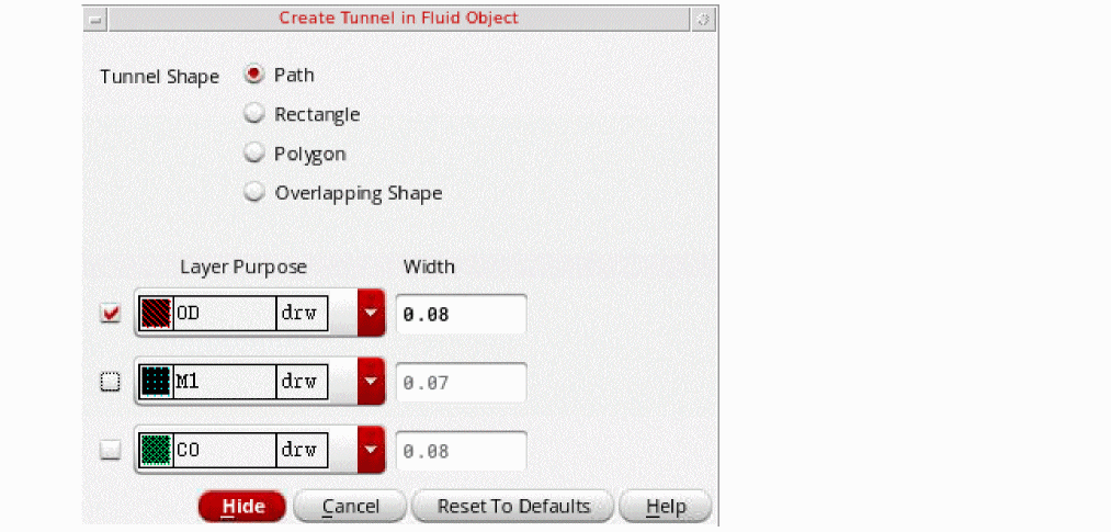
- Against each Layer Purpose row, select the check box for all the layer-purposes through which you want to create the tunnel.
-
For each selected layer-purpose, if required, change the default value in one of the following (whichever is display based on the selected mode): Width, Margin, or Spacing.
The Width, Margin, and Spacing fields for a Layer Purpose are non-editable if the corresponding check box is not selected. -
Click to define the points of a path, rectangle, or polygon that intersect the guard ring or click a shape overlapping the guard ring.You can create a tunnel in a guard ring without selecting the guard ring by using the Overlapping Shape as the Tunnel Shape when the Use Layer-Purpose of the Shape check box is selected.A tunnel is created in the specified area. The area of the tunnel created is determined by the Tunnel Shape you select.
-
Press
Escor click Cancel in the form to finish creating tunnels.
For information about creating tunnels by using the different tunnel shapes, see the following:
- Creating Tunnel By Using the Path Shape
- Creating Tunnel By Using an Overlapping Shape
- Creating Tunnel By Using Rectangle and Polygon Shapes
Creating Tunnel By Using the Path Shape
In the Path mode, you can pre-select or post-select the guard ring. If you do not select any guard ring before starting the command, you are prompted to first select a guard ring and then draw the path points. Tunnels are created through all the selected guard rings that are overlapped by the path you draw.
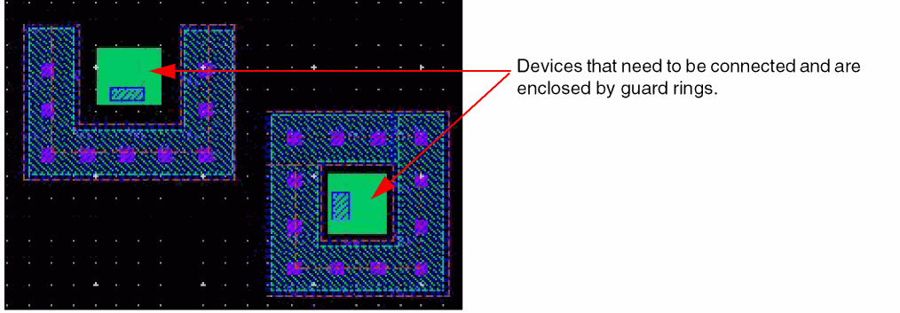
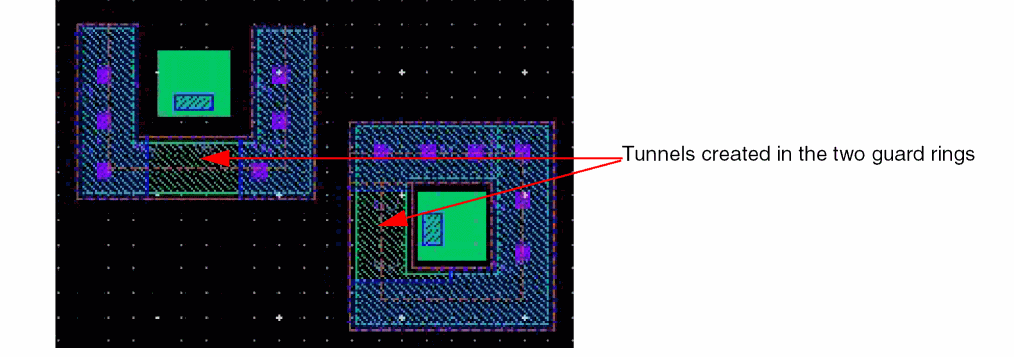
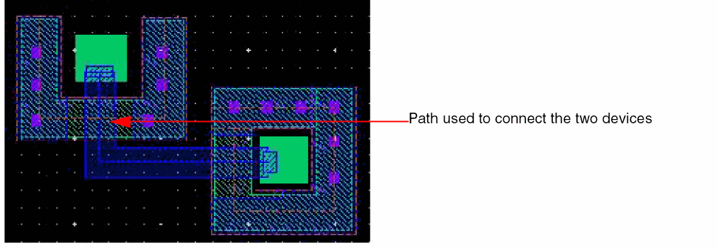
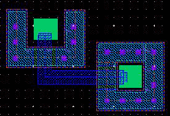
Consider two devices that you need to connect, each of which is enclosed within a guard ring. In this scenario, you can use the Path as the Tunnel Shape to first create tunnels in both the guard rings. Next, place a path to connect the two devices, passing through the tunnel region in the guard rings of the respective devices. This is illustrated below.
-
Select the guard rings.
- Choose Edit – Fluid Pcell – Tunnel.
-
Press
F3.
The Create Tunnel in Fluid Object Form opens. -
Select Path.
All the layer-purposes comprising the two guard rings are listed in the Layer Purpose column. - Select the guard ring layers through which you want to create the tunnel.
- Update the Width column values, if required.
-
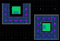
Draw a path intersecting the two guard rings, as shown below.
Tunnels are created in both the guard rings through the selected layers and in the region where the drawn path overlapped the selected guard rings, as shown below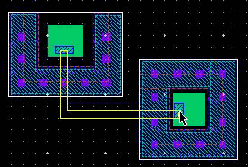
-
Press
Escto finish creating the tunnel.
You can now create a path passing through the created tunnel regions in the two guard rings and connect the two devices.
Creating Tunnel By Using an Overlapping Shape
You can pre-select or post-select a guard ring while using an Overlapping Shape to create a tunnel. In this mode, you can create tunnels even when no guard rings are selected. Tunnels are created in all the guard rings that are overlapped by the shape. If one or more guard rings are selected, tunnels are created through only the selected guard rings that are overlapped by the shape, even if the shape overlaps other guard rings.
In the scenario described in the Creating Tunnel By Using the Path Shape section, you can achieve the same result by drawing an overlapping shape that connects the two devices and create tunnel through both the guard rings by using the overlapping shape.
-
Create a path that connects the two devices.
You can create the path on the same layer-purpose that you want to be removed from the guard ring.
Notice that no guard ring is selected.
- Choose Edit – Fluid Pcell – Tunnel.
-
Press
F3.
The Create Tunnel in Fluid Object Form opens. - Select Overlapping Shape.
- Select the Use Layer-Purpose of the Shape check box.
-
Use the Minimum spacing or specify a value in the User Defined field.
The Minimum spacing for a polygon type guard ring is calculated based on theminSpacingtable rule specified in the technology file corresponding to the layer of the overlapping shape.
The Minimum spacing for a path type guard ring is calculated based on the two-dimensionalminSpacingtable rule withW:Lcalculated as, maximum width: width of the shape of the guard ring path on the same layer as that of overlapping shape. For a path-type guard ring, if only a one-dimensionalminSpacingtable rule is defined in the technology file or the one-dimensionalminSpacingtable rule takes precedence over the two-dimensionalminSpacingtable rule, then the Minimum spacing is calculated based on maximum width specified in the one-dimensionalminSpacingtable rule. -
Click at the path.
The path serves as the overlapping shape. Tunnels are created in the regions where the path overlaps the two guard rings.
-
Press
Escto finish creating the tunnel.
Creating Tunnel By Using Rectangle and Polygon Shapes
In the Path and Overlapping Shape modes, you can specify the exact dimensions of the tunnel to be created. The Rectangle and Polygon modes, on the other hand, provide you with the flexibility of defining a custom tunnel area that is based on the exact points you enter.
In both Rectangle and Polygon modes, you can pre-select or post-select the guard rings. If you do not select any guard ring before starting the Tunnel command, you are prompted to first select a guard ring and then specify the rectangle or polygon points. Tunnels are created through all the selected guard rings that are overlapped by the rectangle or polygon you create.
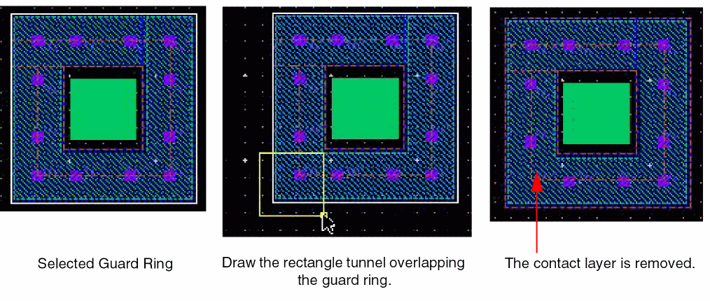
In the following example, the Layer Purpose for the rectangle tunnel is set to the contact layer of the guard ring. If you draw a rectangle to overlap the guard ring, any enclosing contact layer is removed.
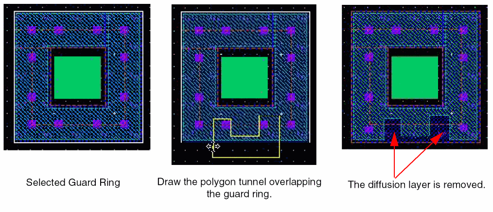
In the following example, the Layer Purpose for the polygon tunnel is set to the diffusion layer of the guard ring. The diffusion layer is removed from the areas where the polygon overlaps the guard ring.
Healing a Fluid Guard Ring
The Heal command removes one or more tunnels from an FGR. For more information about tunnels, see Creating a Tunnel Through a Fluid Guard Ring.
- Choose Edit – Fluid Pcell – Heal.
-
Press
F3.
The Heal Fluid Object Form opens.
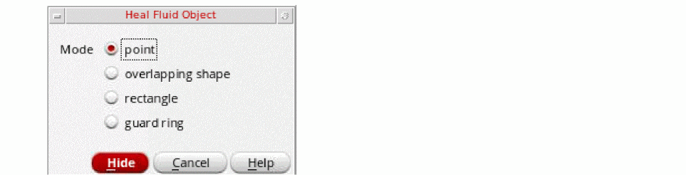
- Select the Mode to be used to heal.
-
To heal by using the selected mode, use the following steps:
- point: Click a tunnel. The tunnel will be removed. You can use this method to remove the tunnels one at a time.
- overlapping shape: Click a shape that overlaps an FGR. All the tunnels overlapping the shape are removed.
- rectangle: Create a rectangle around the FGR instance from which you want to remove the tunnels. This method helps to remove a large number of unrequired tunnels quickly.
- guard ring: Click an FGR instance from which you want to remove all the existing tunnels. This method helps to heal a single FGR at a time.
-
Press
Escor click Cancel in the form to finish healing the FGRs.
Cleaning Overlapped Contacts from Fluid Guard Rings
The Clean Overlapping Contacts command lets you choose whether to clean all the overlapping contacts from an FGR, or just from the area on the canvas that you draw. This command also lets you clean contacts from two overlapping cells that have their FGRs in the hierarchy.
The overlapping contacts are removed without disturbing the placement of the non-overlapping contacts in the overlapping FGR. You can restore the removed overlapping contacts using the Heal command. You can also use the Undo and Redo commands after removing the overlapping contacts.
To clean the overlapping contacts:
-
Choose Edit – Fluid Pcell – Clean Overlapping Contacts.
The Clean Overlapping Contacts Form opens.
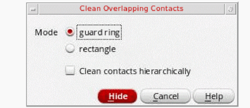
-
Select the guard ring or rectangle radio button from the Mode option.
- When you choose the guard ring button, click the guard ring to remove any overlapping contacts from it.
- When you choose the rectangle radio button, keeping the left mouse button clicked, drag the cursor to select an area of the layout. This removes all overlapping contacts from the selected rectangle.
-
Select the Clean contacts hierarchically check box to clean overlapping contacts from the chosen guard ring while considering the guard rings across all levels of the hierarchy.
When the Clean contacts hierarchically check box is selected, hovering the mouse pointer over the guard ring highlights the guard ring in magenta. It lets you know which guard ring is chosen for cleaning the overlapping contacts. On clicking the guard ring, you get a prompt message to confirm before the guard ring is modified.
Click Yes to modify the guard ring. Click No to cancel the operation.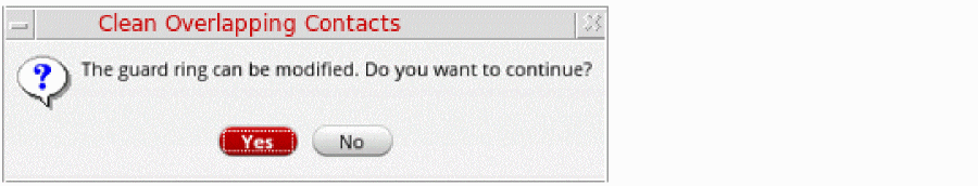
If this option is not selected, overlapping contacts are cleaned from the chosen guard ring while considering only the current level of the hierarchy. - If required, continue to select more overlapping guard rings.
-
Press
Escto finish cleaning overlapped contacts.
Return to top