1
Relative Object Design Concepts
Virtuoso® relative object design (ROD) is a set of high-level functions for defining simple to complex layout objects and their relationships to each other, without the need to use low-level Cadence® SKILL language functions.
This user guide is aimed at CAD engineers and assumes that you are familiar with the development and design of integrated circuits, Virtuoso® Layout Suite L editor, and SKILL programming. This user guide also assumes that you are familiar with the creation of parametrized cells using SKILL or the graphical user interface.
The topics covered in this chapter are:
Using ROD Functions Versus Database Functions
Creating Parameterized Cells with ROD Functions
Stretchable Parameterized Cells
Accessing Stretch Handles in SKILL
Maintaining Connections for ROD Objects
Introduction
Virtuoso® relative object design (ROD) is a set of high-level functions used for defining simple to complex layout objects and their relationships to each other, without the need to use low-level Cadence® SKILL language functions. ROD lets you create objects and define their relationships at a high level of abstraction, so you can concentrate on your design objectives. ROD automatically handles the intricacies of traversing the design hierarchy and simplifies the calculations required to create and align geometries.
A single ROD function call can accomplish a task that otherwise would require several lower-level SKILL function calls. For example, creating a pin required a series of low-level SKILL function calls, but with ROD, you can use a single function to create a shape and designate it as a pin. You can create entities such as guard rings, contact arrays, and transistors with one function call. You can also create an object from an existing object just by specifying the size of the new object.
- Create hierarchical parameterized cells
- Name rectangles, polygons, paths, lines, dots, labels, and text display objects
- Access objects by name through all levels of hierarchy
- Access points and other information stored on objects through all levels of hierarchy
- Align ROD objects to each other or to specific coordinates
- Assign handles to Pcell parameters for interactive stretching
- Create multipart rectangles and multipart paths
- Create objects from other objects
For a complete description of the ROD functions, see Appendix A, “Using Relative Object Design Functions.”
Using ROD Functions Versus Database Functions
This chapter describes in great detail the many advantages of creating and manipulating objects using ROD functions. So, why not make all objects ROD objects? Sometimes, it is better to create an object with a dbCreate function than with a rodCreate function, because the added functionality of a ROD object carries a bit more overhead.
In general, use ROD functions only when you want to:
- Specify persistent relationships between objects
- Create complex multi-part objects, such as guard rings
- Access the object from a different level of hierarchy
- Stretch handles on parameterized cells to change the value of parameters
- Create a new object from an existing object
When you want to create a simple shape, such as a rectangle or simple one-part path, and you do not intend to “relate” the shape to another object, use the dbCreate function. The dbCreate functions do not have to store the additional information required for ROD objects, and therefore, run a little more quickly and use less memory.
Creating Parameterized Cells with ROD Functions
Using ROD functions to create geometries for Pcells increases your productivity by reducing the difficulty and complexity of the code you have to write. To create SKILL Pcells without ROD, you must use low-level SKILL database access functions to build and manipulate geometries. You end up spending a great deal of time and effort calculating and tracking geometry coordinates. Complex SKILL Pcells are much easier to create and maintain when you create geometries with ROD functions. Instead of writing code to compute point coordinates across levels of hierarchy, you create high-level building blocks and align them in relation to each other.
Historically, using programs to create large macro cells and full-chip assemblies required a tremendous effort by SKILL developers who were dedicated exclusively to writing Pcell code. ROD provides high-level design capture support so that even designers with limited programming experience can create complex Pcells, and those with advanced programming abilities can generate sophisticated cells and blocks.
After you capture a design in the form of parameterized code, you can generate a variety of cell modules using different parameter values and different technology rules. Also, creating a single design that captures your intention reduces errors from manipulating low-level layout objects independently of each other.
Major advantages for using ROD to create Pcells are:
- You can base the Pcell parameters on rules from your technology file, making the Pcells tolerant of changes to your technology
- You can assign point handles to Pcell parameters that let you update the parameters interactively by stretching the Pcell in the Virtuoso layout editor
Before you use ROD functions in Pcells, see the safety rules for creating SKILL Pcells in “
For examples of Pcells, see the Sample Parameterized Cells Installation and Reference.
Named Objects
You can assign a name to a zero-level object (an ordinary database shape, such as a rectangle or polygon) either by naming an existing object with the rodNameShape function or by using a RODcreate function to create an object. You can also name a shape when you create it with the Virtuoso layout editor. You can access information through hierarchy about named objects, such as instances and named shapes.
Hierarchical Name
To access information about a named shape or instance through hierarchy, use its hierarchical name and the top-level cellview ID. A hierarchical name consists of the names of the instances through which you need to descend to reach the desired named shape or instance.
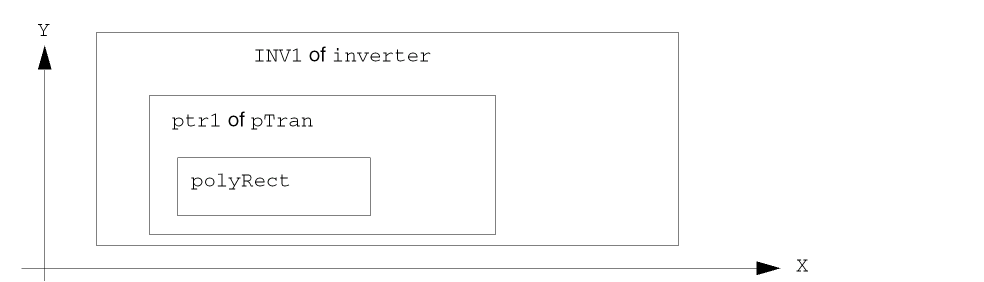
The following figure shows the hierarchy in a layout cellview containing the named shape polyRect. Its hierarchical name is INV1/ptr1/polyRect.
When you name an existing database shape using the ROD naming function, the function creates ROD information associated with the shape. This information is stored in a ROD object and is identified by a unique ROD object ID. The information contained in a ROD object includes its name and database ID. When you create a new shape with a ROD creation function, the function creates a named database shape and a ROD object.
Handles on ROD Objects
A handle is an attribute of, or item of information about, a ROD object, such as the coordinates of a point on the bounding box around an object, the width of the bounding box of an object, or the resistance of an object. You can access handles through all levels of hierarchy.
There are two kinds of handles: system-defined handles and user-defined handles. When you create a ROD object, the system automatically defines a number of handles for the object. The values of system-defined handles are not stored in memory but are calculated on demand when you reference the handles by their names. The values of user-defined handles are stored in memory.
The value of a system-defined point handle is the coordinates for a point on the object or on its bounding box, relative to the coordinate system of the top-level layout cellview. For a detailed description of how the system calculates coordinates through hierarchy, see ROD Objects in Hierarchy.
Using the rodAlign function, you can use handles to align one object to another object to store information, or to access information about an object that is at a lower level in the design hierarchy.
System-Defined Handles
The system automatically defines the following types of handles for most ROD objects:
- Bounding box point handles
- Bounding box width and length handles
- Segment point handles
- Segment length handles
ROD dots, labels, and text display objects are defined by a single point, so all of their point handles evaluate to their origin point and their length and width handles evaluate to zero.
The following table summarizes the types of handles and the ROD object(s) to which they apply.
|
All ROD objects except dots, labels, and text display objects |
|
|
All ROD objects except dots, labels, and text display objects |
|
Bounding Box Point Handles
There are nine system-defined point handles associated with the bounding box around every ROD object:
The system automatically names and calculates values for bounding box point handles. Names indicate the position of the handle, as shown for a polygon in the following figure.
Figure 1-1 Bounding Box Point Handles for a Polygon
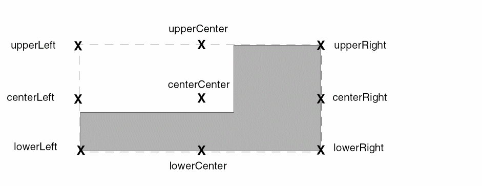
You can abbreviate boundingcR box point handle names as follows:
Bounding Box Width and Length Handles
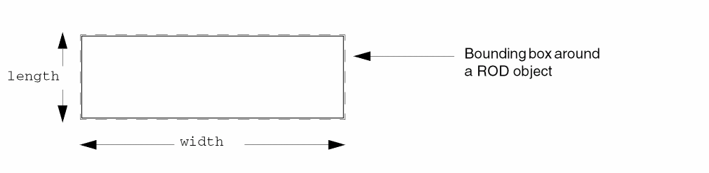
The system provides floating-point handles named width and length for the width and length of the bounding box for a named object, where width is the horizontal measurement and length is the vertical measurement.
For a polygon, the system calculates values for the width and length handles associated with the bounding box, as shown below.
Figure 1-2 Bounding Box Width and Length Handles for a Polygon
For a single-part path, the system calculates values for the width and length handles associated with the bounding box, as shown below.
Figure 1-3 Bounding Box Width and Length Handles for a Single-Part Path
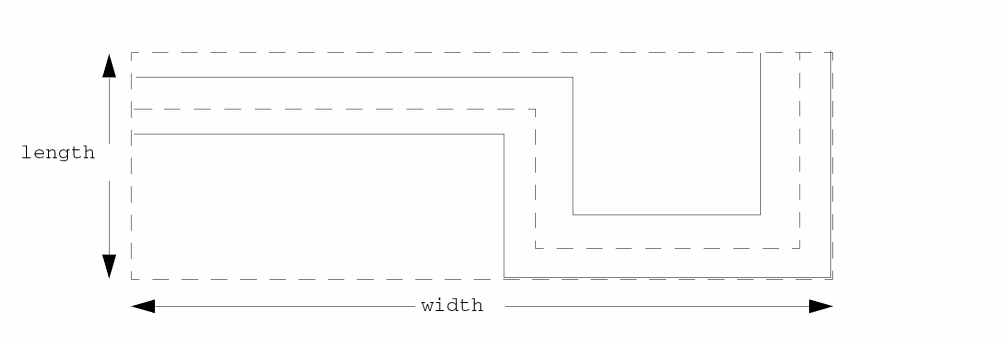
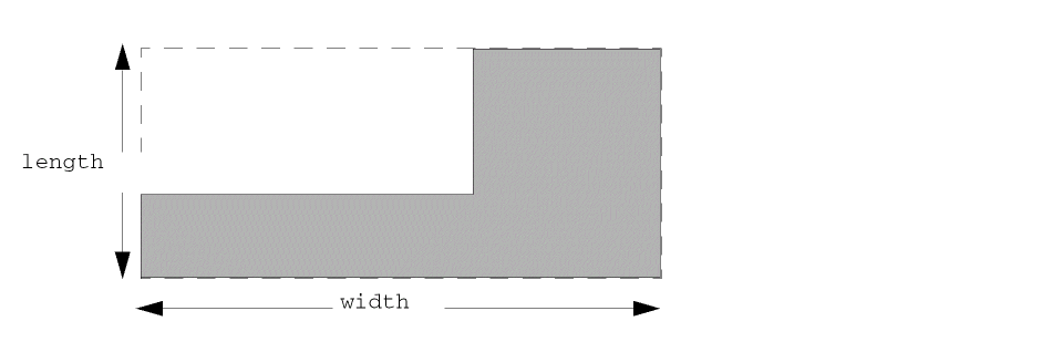
For a multipart path, when the system calculates values for the width and length handles, it always uses the width and length of the bounding box around the master path.
Figure 1-4 Bounding Box Width and Length Handles for a Multipart Path
For multipart paths, there is one additional handle: mppBBox. The mppBBox handle contains a list of the lower-left and upper-right coordinates of the bounding box around the whole multipart path.
Figure 1-5 Bounding Box mppBBox Handle for the Whole Multipart Path
About Segments of Rectangles, Polygons, and Paths
For rectangles, polygons, and paths that are ROD objects, the system assigns several point handles to each segment of the object. You can use these segment point handle names to reference points on the boundary of the object.
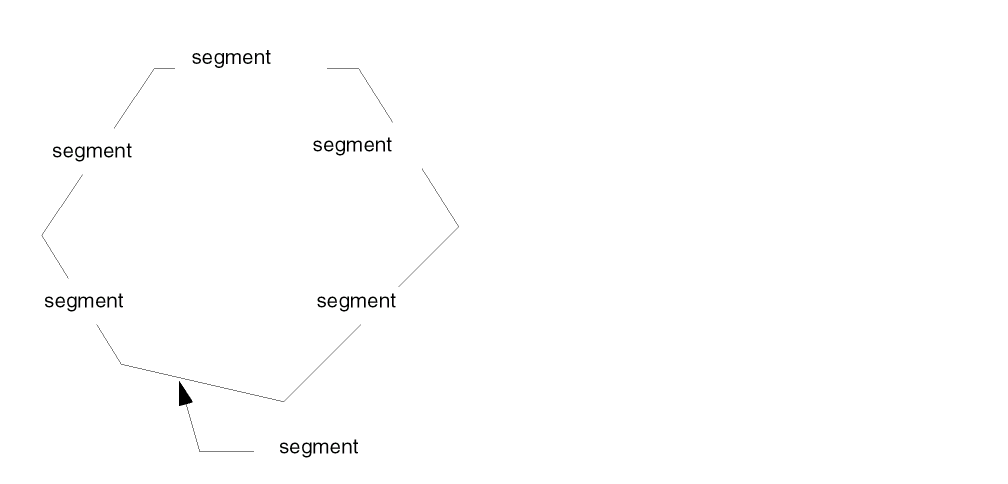
For relative object design, a segment of a rectangle or polygon is defined as an edge, or finite line between two points, partially forming the boundary of the object. For example, a six-sided polygon has six segments (six edges).
Figure 1-6 Segments of a Polygon
For paths, segments include the width of the path and both edges. For example, the following path has four segments.
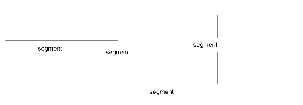
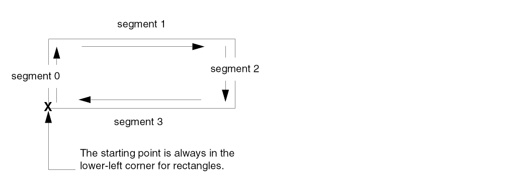
The system assigns a name to each segment of the object, using the prefix segment followed by a number: segmentn, where n begins at zero and is the segment number. For ROD rectangles, segments are always numbered as if they were defined in a clockwise direction, starting in the lower-left corner.
Figure 1-8 Numbering the Segments of a Rectangle
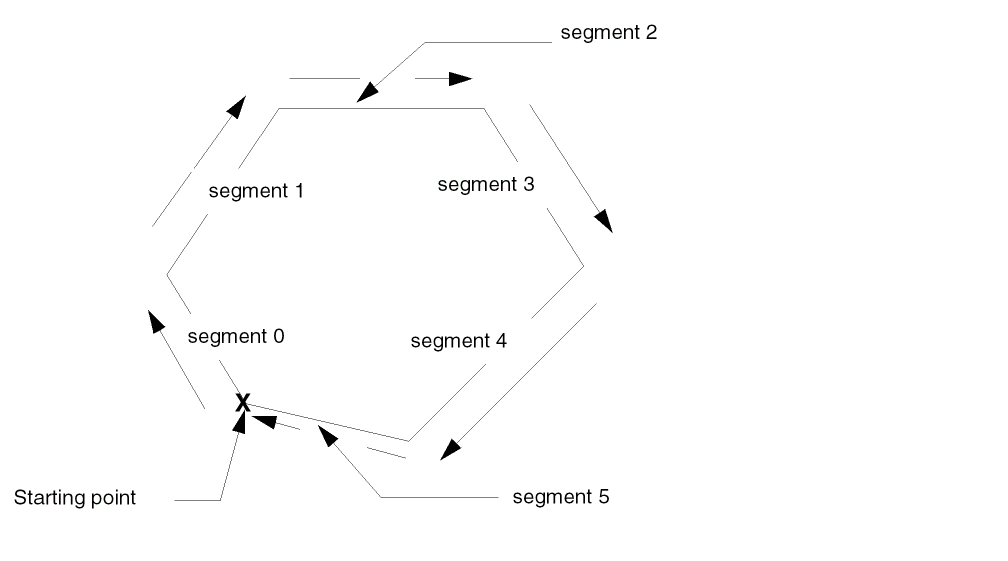
For ROD polygons, the system numbers segments in the direction in which the polygon was created, starting with the first point defined. The six-sided polygon below was created in a clockwise direction.
Figure 1-9 Numbering the Segments of a Polygon
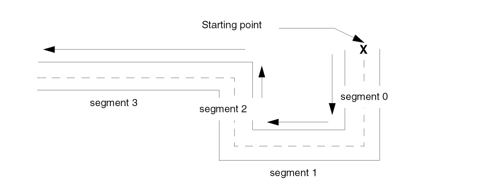
rodNameShape function, the system numbers segments starting with the first point you defined when you created the polygon.The segments of the path below were created in a clockwise direction.
Figure 1-10 Numbering the Segments of a Path
Segment Point Handles for Polygons and Rectangles
For rectangles and polygons, the system calculates the following point handles:
-
For each segment, three point handles: one at the beginning, middle, and end of the segment. Their names are:
startn,midn, andendn, where n is the segment number. Theendn handle for a segment and thestartn handle for the next segment share the same point. -
For the last segment, the three handles described above, plus three more handles:
startLast,midLast, andendLast.
The six-sided polygon in the following figure was created starting in the upper-left corner of the highest segment, with the segments defined clockwise.
Figure 1-11 Segment Point Handles for a Polygon
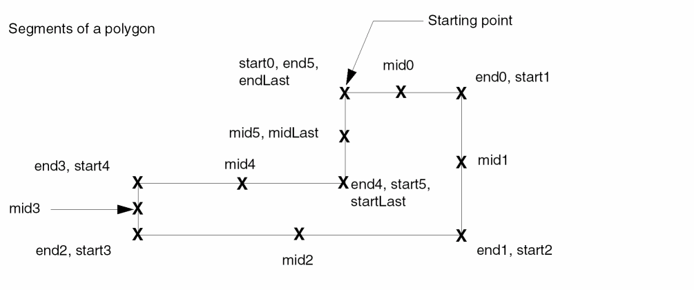
The starting point of the first segment is also the ending point of the sixth segment, so the value of the start0 point handle is the same as the value of the end5 point handle. The system calculates values for three additional point handles for the last segment of the polygon, which in this case is the sixth segment. The illustration shows three system-defined segment point handles—start0, end5, and endLast—for the same point.
For rectangles, the system always uses the lower-left corner as the starting point and defines segments in a clockwise direction.
Figure 1-12 Segment Point Handles for a Rectangle
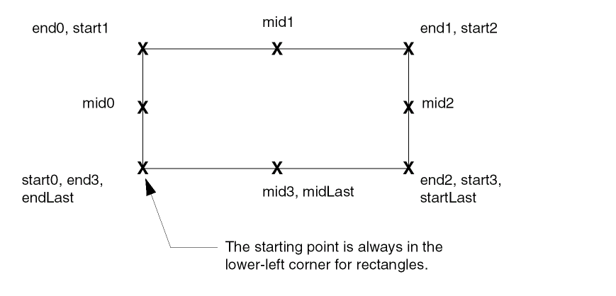
For rectangle, the lower left corner is always its starting point, so when you rotate a rectangle, the handle values change.
Segment Point Handles for Paths
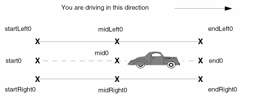
When naming segment point handles for paths, the system takes into account the direction of the path. The names of handles on the left in relation to the direction of the path contain the word Left, and the names of handles on the right contain the word Right.
For example, if the single segment below was a road, and you were driving on it in the direction shown, then the handles on the top edge of the segment are named Left segment handles and handles on the bottom edge of the segment are named Right segment handles.
Figure 1-13 Segment Point Handles for a Single-Segment Path
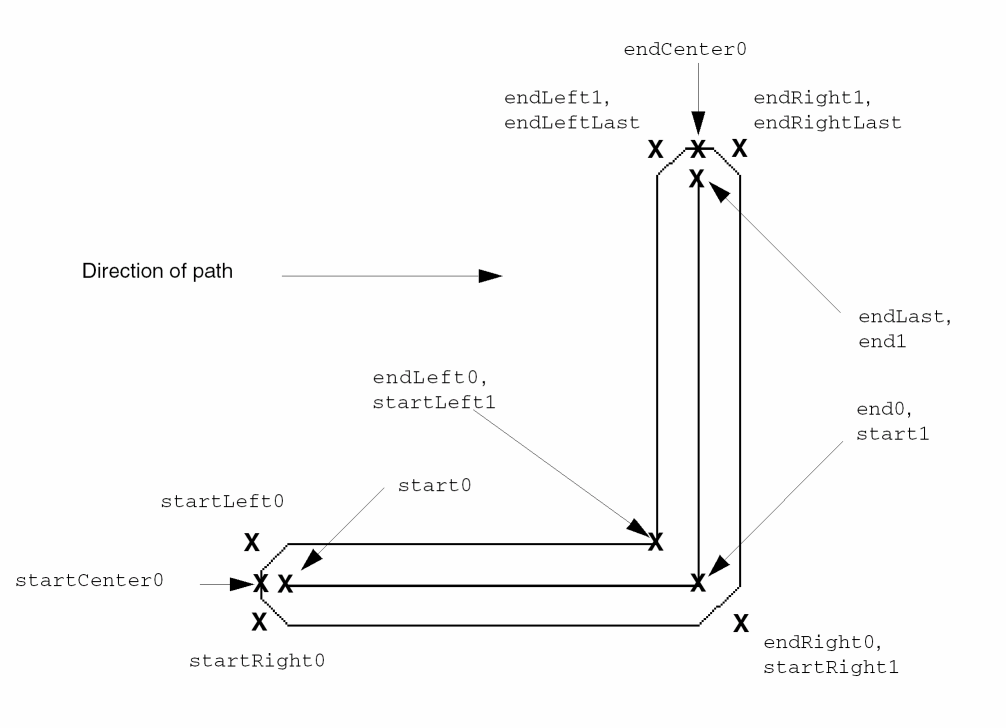
The point handle names for a multisegment path are shown below.
Figure 1-14 Segment Point Handles for a Multisegment Path
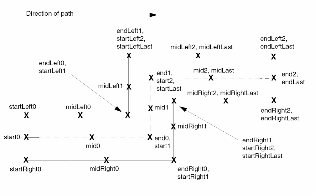
For paths, the system calculates the values of two additional point handles: startCenter0 and endCenterLast.
For paths with the end type flush, the startCenter0 and endCenterLast handles have the same values as the start0 and endLast handles. However, for paths with the layer extending beyond the centerline, which have an end type of variable, offset, or octagon, the startCenter0 and endCenterLast handles have different values than the start0 and endLast handles, as shown in the following figure.
Figure 1-15 Point Handles for Extended-Type Paths
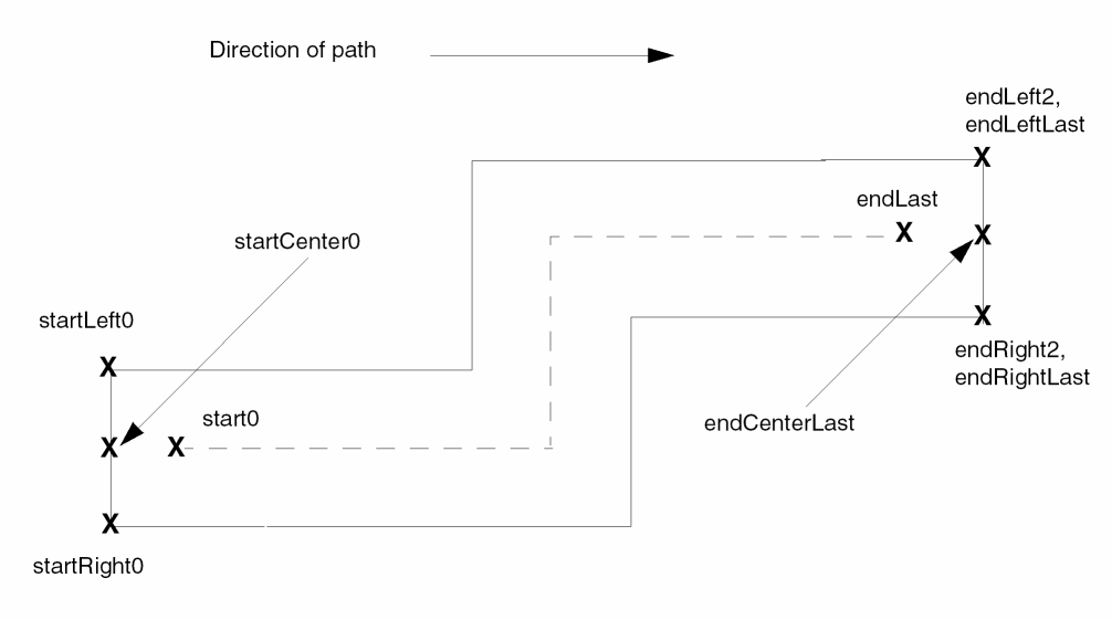
For paths with an end type of flush, offset, or variable, segment point handles are on the path boundary or path centerline. However, for paths with the end type octagon, some segment point handles at the path ends and where path segments join are outside the path boundary.
For example, for the following path, the startLeft0, startRight0, endRight0, startRight1, endLeft1, endLeftLast, endRight1, and endRightLast segment point handles are located outside of the path itself.
Figure 1-16 Segment Point Handles for Paths with Octagonal Ends
Segment Length Handles
The system provides one segment length handle for each segment for objects that have segments. For paths, the system provides a length handle for the centerline of each segment, excluding extensions, if any.
mppBBox handle.
The system names length handles lengthn, where n is the segment number. The handle for the length of the first segment is length0. The system increases n by 1 for each additional segment, in the direction in which the object was created. (Rectangles are always created in a clockwise direction, starting in the lower-left corner.) The system also provides the handle lengthLast for the last segment.
Figure 1-17 Segment Length Handles for a Rectangle
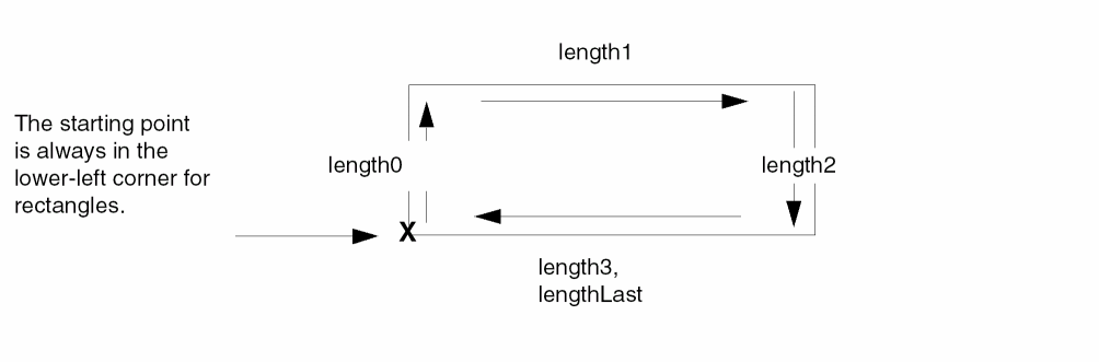
For rectangle, the lower left corner is always its starting point, so when you rotate a rectangle, the handle values change.
The six-sided polygon in the following figure was created starting in the upper-left corner of the highest segment, with the segments defined clockwise.
Figure 1-18 Segment Length Handles for a Polygon
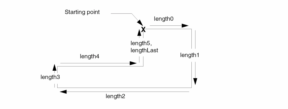
rodNameShape function, the system numbers segments starting with the first point you defined when you created the polygon.For a path, the system computes values for segment length handles along the path centerline. The names of segment length handles for a four-segment path are shown next.
Figure 1-19 Segment Length Handles for a Multisegment Path
Accessing the Path Width
The system does not automatically compute the value for the width of a ROD path. (The width handle measures the width of the bounding box around a path.) However, you can access the path width by using the dbId) with the database access operator (~>).
For a multipart path, for example, the following statement returns the width of the master path:
rodId~>dbId~>width
Why Are There Multiple Handles for the Same Point?
In some cases, the system provides more than one handle for the same point. Although multiple handles for the same point might seem redundant, they provide you with flexibility. For example, if you do not know the number of segments an object has, you can refer to points on the last segment by using point handle names containing the word Last.
For example, for an eight-sided polygon created in a clockwise direction, with the starting point in the upper-right corner, the segments are numbered segment 0 through segment 7.
Figure 1-20 Multiple Handle Names for the Same Point
User-Defined Handles
You can define your own handles to store points, calculations, and other information. When you define a new handle, you specify the name (or let it default) and assign a value. The values of user-defined handles are stored in the database. The information stored can have any of the following data types:
If you let the name of your new handle default, the system assigns a name unique within the cellview, as follows: handle0, handle1, handle2, etc.
For example, if a layout cellview contains two ROD objects, and you create one user-defined handle for each object without specifying handle names, the system assigns the name handle0 to the handle on the first object and handle1 to the handle on the second object.
If you create a handle without specifying a name, you can find out what the system named the new handle. For a code example showing how to do this, see Problem 3-6 Querying a System-Assigned Handle Name.
Aligning Objects
You can specify the position of one named object in relation to another named object with the rodAlign function. This is called relative alignment.
To align two named objects, identify the object you want to align (aligned object) and the object or point you want to align it to (reference object or reference point). Usually, you align objects by specifying a point handle on each object. You can also specify the distance between the two objects in the direction of the X axis, the Y axis, or both.
The alignment between two objects is preserved when you manipulate either object and when you save and close the layout cellview. For example, when you move a reference object, the aligned object moves with it.
An alignment can involve any named geometry at any level of hierarchy and any design rule that is defined in your technology file.
For example, you can align a point handle on object B to a point handle on object A (the reference object) and specify the distance between them as equal to the minimum design rule for the layer in your technology file. When you move object A, object B also moves, and vice versa.
Or you might want to align the centerLeft point handle on the object named D in the instance nTrans2 to the centerRight point handle on the reference object, B in the instance nTrans1.
When Are ROD Alignments Recalculated?
The system automatically calculates and applies alignments for named objects whenever
- A layout cellview is opened in edit mode
- Either object involved in an alignment is edited in any way (moved, rotated, stretched, etc.), at any level of the hierarchy
- You reload your technology file
When you open a cellview in edit mode, the system automatically calculates and applies all alignments assigned to the ROD objects in the cellview.
Separating Aligned ROD Objects
You can specify the separation for ROD objects in the direction of the X axis, the Y axis, or both. Usually, one or more design rules determines the value of the separation.
You can use a SKILL expression with technology file variables to calculate the separation across one or more levels of hierarchy. The system automatically reevaluates SKILL expressions used in alignment whenever it needs to recalculate the alignment.
ROD Objects in Hierarchy
When you access a point handle associated with a ROD object with the rodGetHandle function or the ~>), the system automatically transforms (converts) the coordinates of the point up through the hierarchy into the coordinate system of the top-most cellview containing the object. You specify levels of hierarchy in the name of the object.
The following example shows a cellview, CCC, containing two levels of hierarchy. The first level contains the instance IB1 of cell BBB; the second level contains two instances of AAA and some zero-level objects that are not shown.
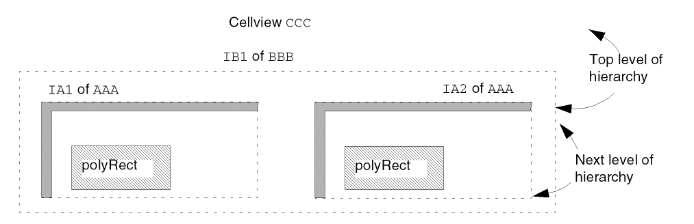
The hierarchical name for the shape polyRect in instance IA1 of AAA, where instance IA1 is in the instance IB1 of BBB, is
IB1/IA1/polyRect
The hierarchical name for the shape polyRect in instance IA2 is
IB1/IA2/polyRect
For detailed examples showing how to access objects through hierarchy, see Using rodGetObj.
Querying Objects for Alignments
You can query any named object to see what the object is aligned to. When you query a hierarchical object, the system displays all top-level alignments for the object.
To see the alignments for an object, you can use the Virtuoso layout editor Edit Properties command (click ROD at the top of the form) or type commands in the CIW. For an example showing how to query an object in the CIW, see Examples of Using ~> to Display Information.
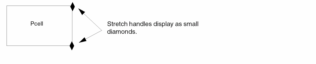
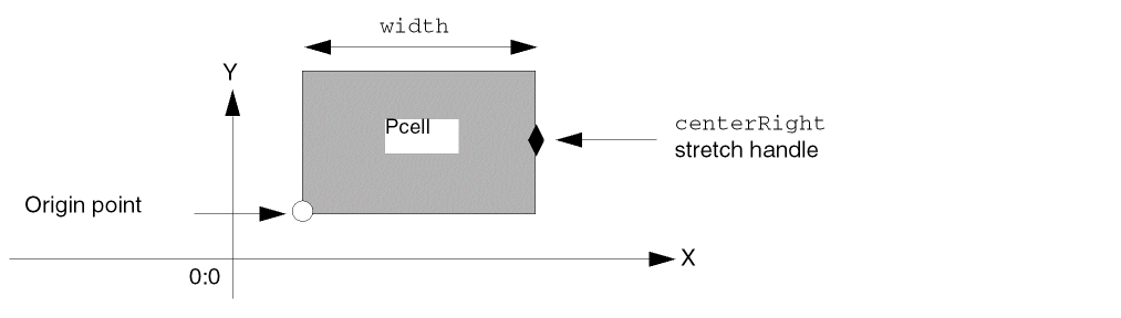
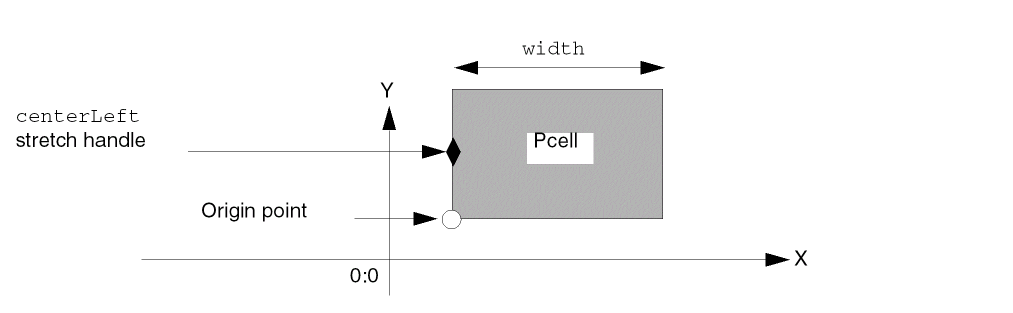
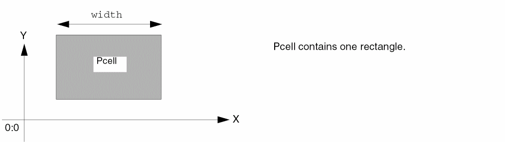
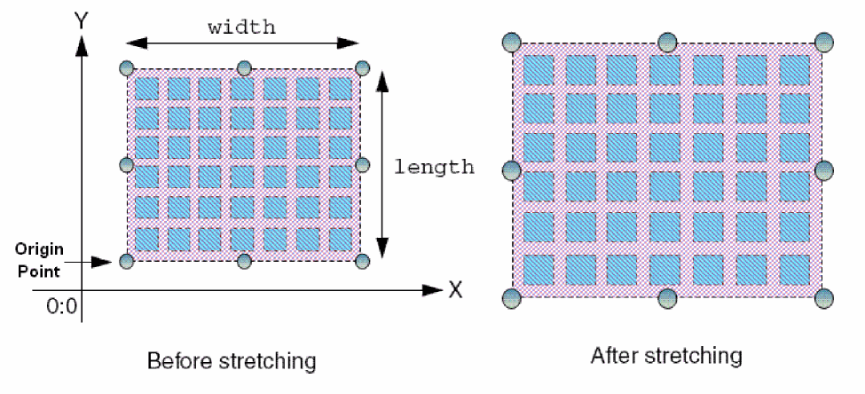
Stretchable Parameterized Cells
When you create a SKILL Pcell, you can make its instances “stretchable” by assigning point handles to the parameters of the Pcell with the rodAssignHandleToParameter function. This kind of handle is called a stretch handle.
You can also make Pcell custom vias stretchable.
A Pcell with stretch handles is called a stretchable Pcell. Assigning stretch handles to Pcell parameters lets you graphically change the value of those parameters for Pcell instances after you place them. You do this by selecting one or more handles and using the Stretch command. A handle is selectable when its layer-purpose is defined in the cellview where the Pcell is instantiated. Max number of drag figures applies to the stretch.
You are not stretching objects within the Pcell or stretching the Pcell itself. Instead, you are graphically updating the value of the parameters associated with the selected handles. Graphically stretching a Pcell instance has the same result as editing its parameters using the Edit Properties form.
For more information about point handles, see Handles on ROD Objects.
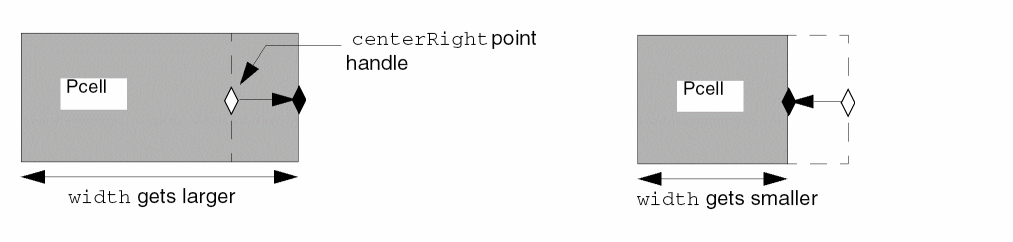
You specify the direction in which a handle stretches as either X or Y. For example, if you have a Pcell containing a single rectangle and want to stretch the width of the rectangle, you could assign the centerRight point handle to the width parameter of the Pcell and specify a stretch direction of X. This lets you change the value of the width parameter by stretching the centerRight point handle horizontally.
When you assign a handle to a parameter, you can define your own function to calculate the value of the Pcell parameter to which you are assigning the handle. The system passes the increment or decrement resulting from stretching the assigned handle(s) to the user-defined function as input and uses the value returned by the function to replace the value of the parameter.
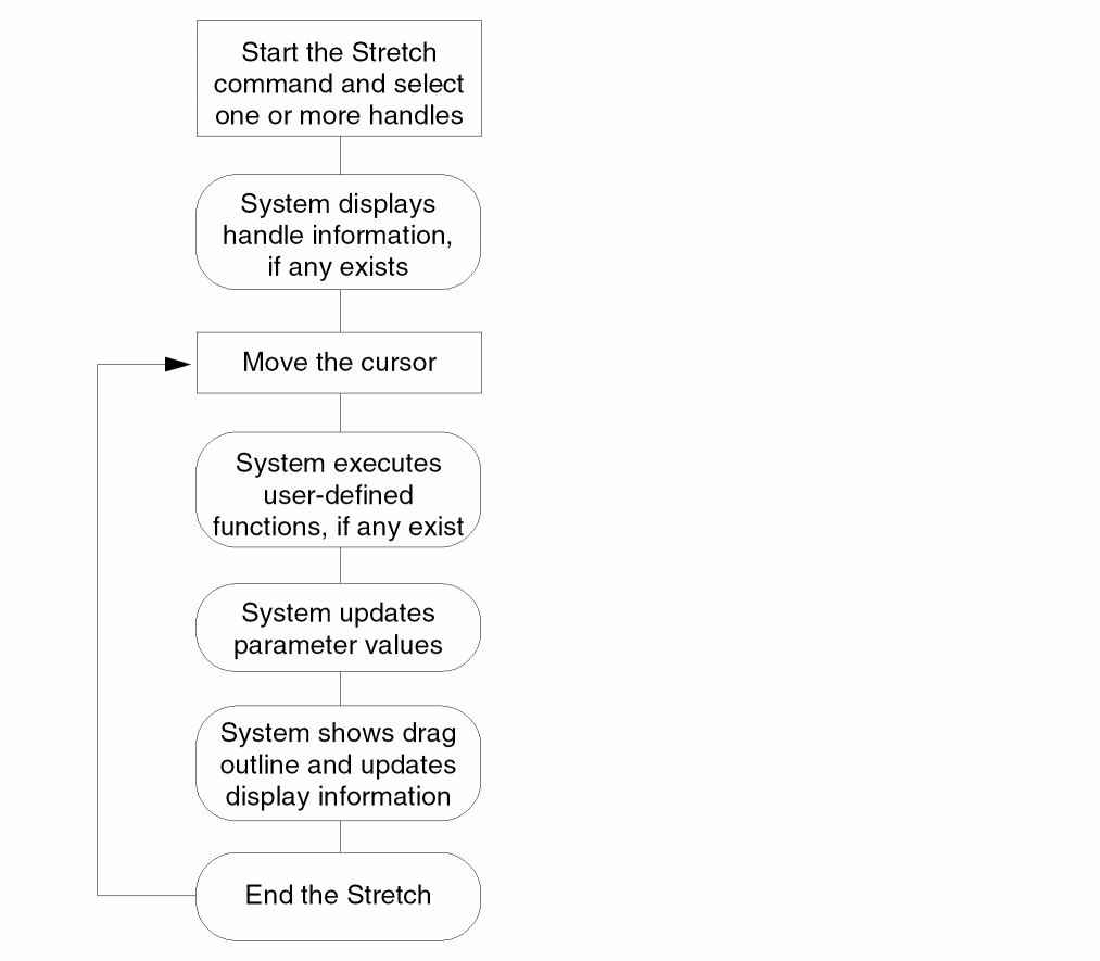
The Stretchable Pcell Process
The process for stretching Pcells is described below.
-
Start the Stretch command and select one or more stretch handles.
- Click to indicate the new location.
The system does the following:
- When you first select a stretch handle (or more than one stretch handle) for which there is display information specified, such as a parameter name and value, the system shows the information next to the upper-right corner of the Pcell.
-
As you move the cursor, the system does the following, in the sequence in which the handle-to-parameter assignments are specified in the Pcell code and according to the frequency specified for regenerating the Pcell:
- When there are no user-defined functions associated with the handles, the system applies the increment or decrement directly to the value of the parameters.
- When there are user-defined functions, the system sends the increment or decrement to the user-defined functions, executes the functions, and replaces the value of the parameters with the values returned by the functions.
- Displays an outline of the regenerated Pcell and updates the information displayed, if any.
The steps of this process repeat until you complete the stretch. For a flowchart of the process, see Figure 1-21.
Figure 1-21 Flowchart for the Stretchable Pcell Process
Assigning Handles
To make a Pcell stretchable, in your Pcell code, you can assign
- One point handle to one parameter
- Multiple point handles to one parameter
- One point handle to multiple parameters
- Three point handles at once by specifying an edge
To assign handles to parameters, use the rodAssignHandleToParameter function. In each rodAssignHandleToParameter statement, you can assign one or more point handles to one parameter and specify one stretch direction (X or Y). To assign a handle to multiple parameters, you must write multiple rodAssignHandleToParameter statements for the Pcell.
Assigning Multiple Handles to One Parameter
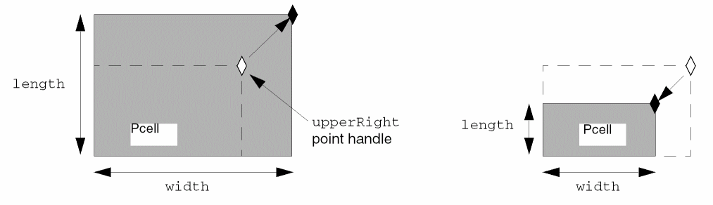
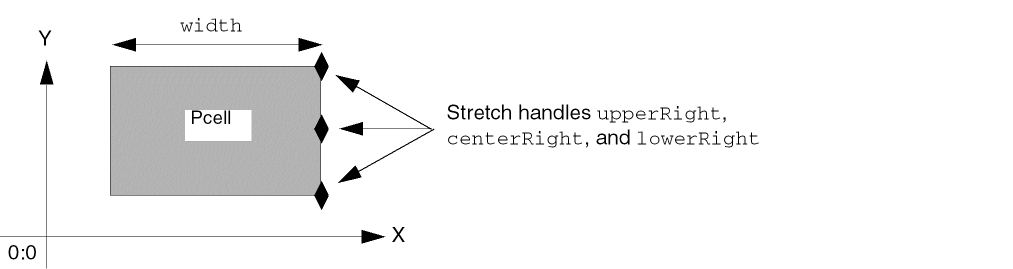
You can assign more than one handle to one parameter. For example, if you assign the upperRight, centerRight, and lowerRight point handles to the width parameter of a Pcell that contains only a rectangle and specify a stretch direction of X, then you can change the value of the width parameter by stretching any or all of the three point handles horizontally.
Assigning One Handle to Multiple Parameters
You can assign one handle to two or more parameters. When you stretch the handle, the stretch might affect more than one of the associated parameters.
For example, if you want to use one handle to stretch an object in the direction of both the X and Y axes, you assign the same handle to two parameters by writing two rodAssignHandleToParameter statements. In one statement, you assign the handle to the first parameter with a stretch direction of X, and in the other statement, you assign the same handle to a second parameter with a stretch direction of Y.
The following example shows a Pcell containing only a rectangle. You could assign the upperRight point handle to the width parameter with a stretch direction of X, and assign the upperRight point handle again to the length parameter with a stretch direction of Y. Then you can change the value of the width parameter by stretching the upperRight point handle horizontally as shown in a previous example and change the value of the length parameter by stretching the upperRight point handle vertically.
Assigning the same handle to two different parameters requires two separate rodAssignHandleToParameter statements.
You can also change the value of both the width and length parameters by stretching the upperRight point handle at any other angle.
Assigning Handles by Specifying Bounding Box Edges
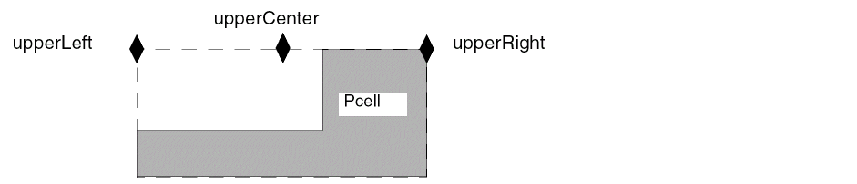
You can assign three bounding box point handles for a ROD object to a Pcell parameter at once by specifying the name of the bounding box edge. Specifying an edge automatically assigns all three point handles on the edge to the same parameter. For example, for a rectangle that is a Pcell, the bounding box edges you can specify are upperEdge, lowerEdge, leftEdge, rightEdge.
When you specify upperEdge, you simultaneously specify the three point handles on the bounding box: upperLeft, upperCenter, and upperRight.
Specifying Environment Variables for Stretchable Pcells
You can set the environment variables listed below to influence what the system does when you stretch a handle:
-
updatePCellIncrementA floating-point layout editor environment variable specifying how often the system updates Pcell parameters and regenerates the Pcell during a stretch operation. The default is at every grid snap, as defined by the technology file variablemfgGridResolution.
If you want to vary the update frequency for different handle-to-parameter assignments within the same Pcell, you can specify the f_updateIncrement argument for therodAssignHandleToParameterstatement for each handle-to-parameter assignment. The value of the f_updateIncrement argument overrides the value of the layout editor environment variableupdatePCellIncrement. -
displayStretchHandlesA Boolean graphic editor and layout editor environment variable specifying whether stretch handles are displayed in layout cellviews. The default ist, which displays stretch handles. -
stretchHandlesLayerA string graphic editor environment variable specifying the layer on which stretch handles are displayed. The default is they0layer anddrawingpurpose. -
stretchHandleShape
A cyclic environment variable to control the default shape of the stretch handle when it is not specified through theS_shapeargument of therodAssignHandleToParameterSKILL function. Valid values arediamond,square, ordot.
For a description of how to set graphic editor and layout editor environment variables, see
Specifying the Frequency of Pcell Regeneration
You specify how often the system updates Pcell parameters and regenerates the Pcell during a stretch operation with the f_updateIncrement argument. You can also use the layout editor environment variable updatePCellIncrement to control the frequency of Pcell regeneration. The default for both is to update the Pcell parameters and regenerate the Pcell at every grid snap, as defined by the mfgGridResolution variable in your technology file.
Results of Stretching a Handle
The results you get from stretching a handle depend on the code written for the Pcell, including
- Where the stretch handle is located
- Whether stretching the handle affects the instance boundary
- Whether the origin point of the instance is allowed to move
- How the stretch direction and stretch type are specified
- The data type of the parameter to which the handle is assigned
- Whether the parameter value is computed by a user-defined function
- Whether the instance is rotated
- The settings of the environment variable that influence stretchable Pcells
- How often the system regenerates the Pcell
Results of Specifying the Stretch Type
The stretch type determines whether the parameter is increased or decreased in relation to the stretch direction. The stretch type can be either relative or absolute.
- For a stretch type of relative, the stretch is in relation to the center of the Pcell.
- For a stretch type of absolute, the stretch is in relation to the X or Y axis.
The results of a stretch often depend on whether or not the origin point of the Pcell instance can move. The origin point is usually the lower-left corner. For handles in some locations, the results of a stretch are the same for both stretch types, whether the origin point can move or not.
In the following examples, the Pcell contains a single rectangle, so handles on the bounding box of the rectangle are also on the boundary of the instance. There are no user-defined functions.
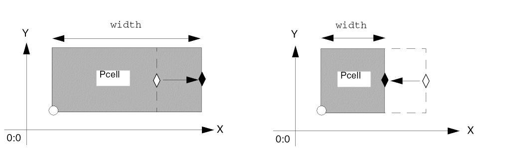
In the example below, the centerRight point handle of a rectangle is assigned to the width parameter of the Pcell with the stretch direction X. The width parameter controls the width of the rectangle.
For this sample Pcell, stretching to the right always increases width no matter what the stretch type is and whether or not the origin point can move, because the handle is located in the middle of the right edge. Conversely, stretching to the left always decreases width for this Pcell.
However, for handles in most locations, the results of stretching are different for each stretch type and when the instance origin point can move or not move.
Results for the Relative Stretch Type
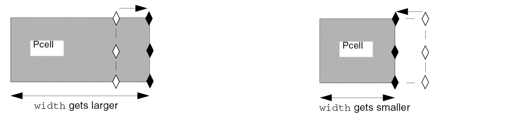
For a stretch type of relative, stretching a handle away from the center of its ROD object increments the associated Pcell parameter, while stretching towards the center of the ROD object decrements the associated Pcell parameter. A stretch away from the center makes the object larger and a stretch towards the center makes the object smaller.
The results of stretching a handle might vary depending on whether the instance origin point can move during a stretch. In the example below, the centerLeft point handle on the rectangle is assigned to the width parameter of the instance, with a stretch direction of X. The Pcell contains only the rectangle.
When you stretch the centerLeft handle to the left (away from the center of the Pcell), the width parameter is incremented, so the width of the rectangle and instance gets larger.
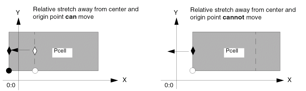
In both cases, the width of the rectangle and instance gets larger. However, if the instance origin point cannot move, the width of the rectangle and instance expands to the right.
For a relative stretch, when you stretch the centerLeft handle to the right (towards from the center of the Pcell), the width parameter is decremented, so the width of the rectangle and instance gets smaller.
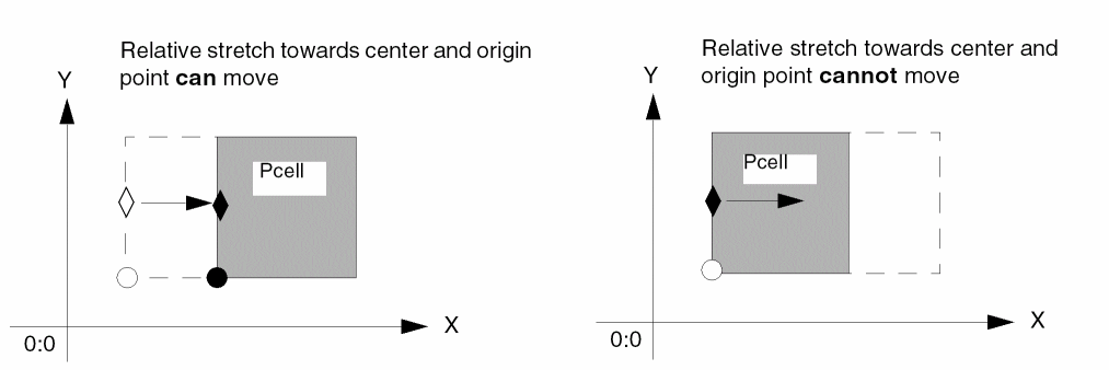
In both cases, the width of the rectangle and instance gets smaller. However, if the instance origin point cannot move, the width of the rectangle and instance shrinks from the right.
Results for the Absolute Stretch Type
For a stretch type of absolute, stretching in a positive direction in relation to the X or Y axis increments the associated Pcell parameter, while stretching in a negative direction decrements the associated Pcell parameter.
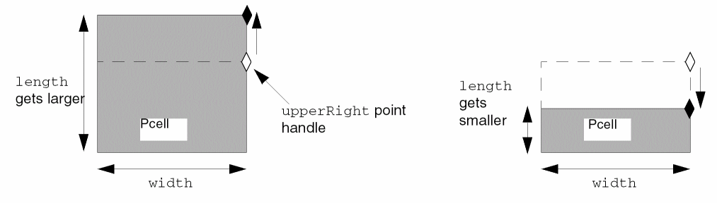
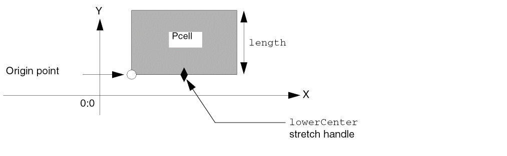
The results of stretching a handle might vary depending on whether the origin point can move during a stretch. In the example below, the lowerCenter point handle is assigned to the length parameter of a rectangle that comprises a Pcell. The stretch direction is specified as Y.
For an absolute stretch, when the stretch handle is on the bottom of the object and you stretch upward (in a positive direction along the Y axis), the length parameter is incremented, so the object gets larger. How the rectangle expands depends on whether the origin point can move.
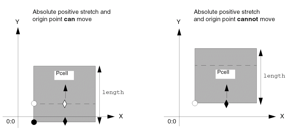
When the origin can move, the edge on which the handle is located can move also, which allows the handle to move during the stretch. An absolute stretch of the lowerCenter point handle upward along the Y axis increases the length parameter, making the rectangle and instance larger by moving the edge on which the handle is located.
When the origin cannot move, the edge on which the handle is located cannot move either, which prevents the handle from moving during the stretch. An absolute stretch of the lowerCenter point handle upward along the Y axis increases the length parameter, making the rectangle and instance larger by moving the edge opposite from where the handle is located.
For an absolute stretch, when the handle is on the bottom of the object and you stretch downward (in a negative direction along the Y axis), the length parameter is decremented, so the object gets smaller. How the rectangle shrinks depends on whether the origin point can move.
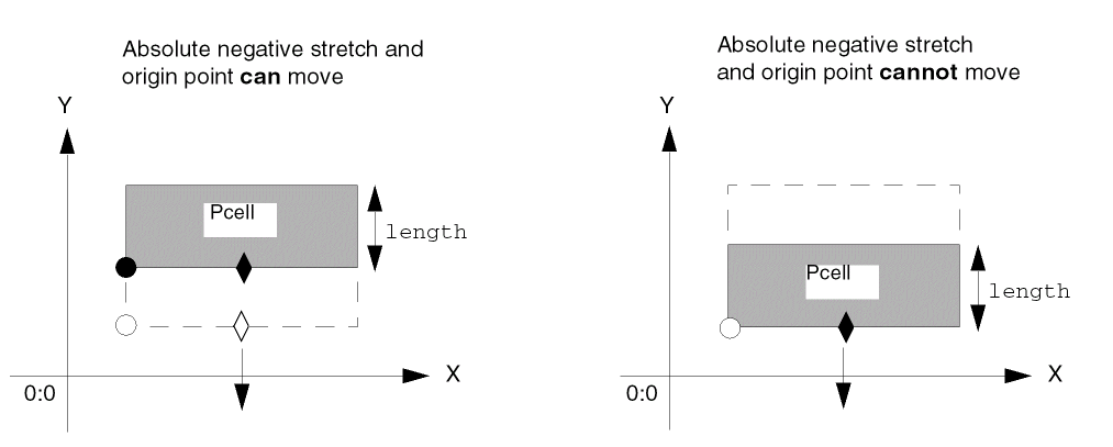
In both cases, the length of the rectangle and instance get smaller. When the origin can move, an absolute stretch of the lowerCenter point handle downward along the Y axis decrements the length parameter by moving the lower edge of the rectangle. However, when the origin cannot move, an absolute stretch decrements the length parameter by moving the edge opposite from where the handle is located.
Results of Stretching Multiple Handles
When you select more two or more handles to stretch at the same time, the system processes each handle in the sequence in which the handle-to-parameter assignments appear in the Pcell code. The results depend partly on how the handles affect Pcell parameters.
- When the selected handles are assigned to the same parameter and affect that parameter in the same way, the system applies only the change to the parameter from the handle that appears first in the handle-to-parameter assignments in the Pcell code; the system ignores the results of stretching the other handles.
- When the selected handles are assigned to the same parameter but affect the same parameter in different ways, the system applies the change from each handle to that same parameter, cumulatively.
- When the selected handles affect different parameters, the system applies the change from each handle to each parameter individually.
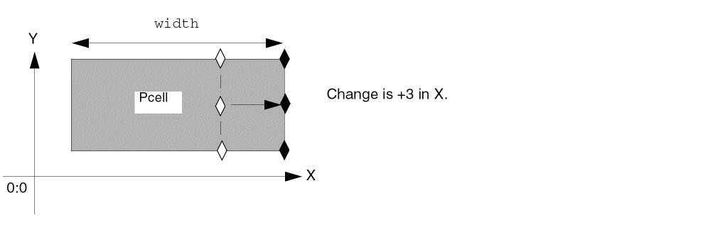
In the following example, the Pcell contains a single rectangle. There are no user-defined functions for the handles.
The three point handles, upperRight, centerRight, and lowerRight, are all assigned to the width parameter of the Pcell with the stretch direction of X. The width parameter controls the width of the rectangle.
When you stretch by +3 along the X axis, all three point handles affect the width parameter in the same way, so stretching all three handles gets the same result as stretching only one or two of the handles.
Stretching Multiple Handles on the Same Point
When there are multiple stretch handles on the same point, and you select that point (or one of the handles on it), all stretch handles on the point are selected.
Results of Dragging a Handle During a Stretch
As you move the cursor during a stretch operation, the system displays an outline of the instance and shows how it is changing. If you want to see an outline of each individual object in the Pcell and the Pcell boundary, you can turn on the Drag Enable property for the object layers. You can set this property by choosing the Technology File – Edit Layers command in the Command Interpreter Window.
Replace CDFs with User-Defined Functions
In this release, stretching a Pcell does not execute CDFs associated with the Pcell parameters. For now, you should use user-defined functions to perform tasks formerly performed by CDFs.
For more information about user-defined functions, see “Sl_userFunction argument description for the rodAssignHandleToParameter function.
Example of Stretching a Sample MOS Transistor
The following Pcell contains a MOS transistor with two contact arrays.
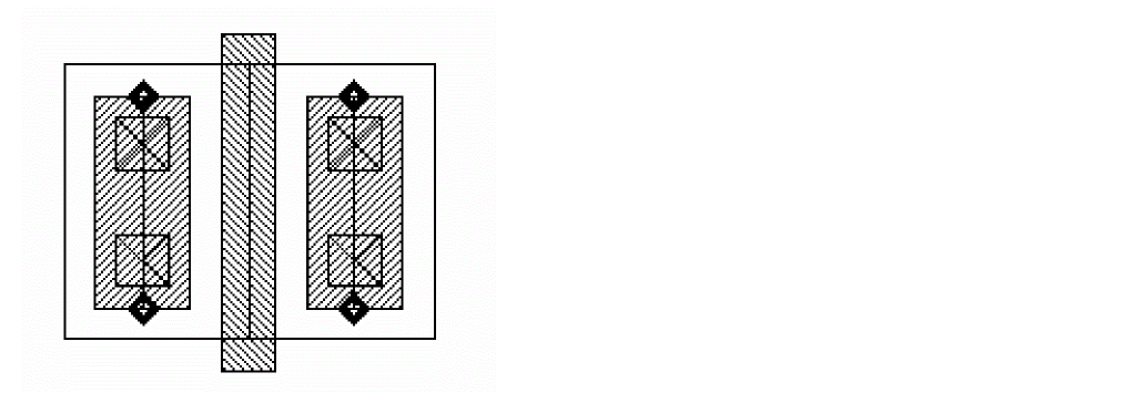
You can stretch the MOS transistor in a negative direction towards the Y axis to reduce the number of contacts in the array from two to one, using the Virtuoso layout editor Stretch command.
- Choose Edit – Stretch.
-
Select the
upperCenterstretch handle on the left contact array using an area-selection box. -
To enter the reference point, click the
upperCenterstretch handle on the left contact array.
The following information appears to the right of the Pcell:leftcov = 1As you move the cursor down, the information changes toleftcov = 0.25 -
To enter the new location, click above the bottom transistor.
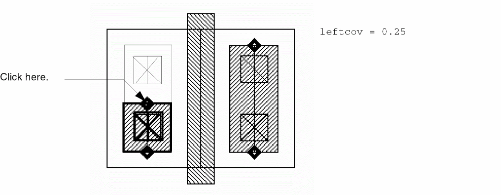
-
Exit the Stretch command by pressing
Escape.
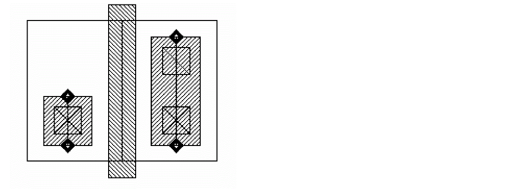
The MOS transistor Pcell instance now looks like this:
Displaying Pcell Stretch Handles
You can control whether Pcell stretch handles display either with the layout editor Display Options form or by setting the graphic editor and layout editor environment variable displayStretchHandles in the CIW. The default is to display stretch handles.
To specify the layer on which stretch handles are displayed, set the graphic editor environment variable stretchHandlesLayer.
Stretch PCell Custom Vias
Like multi-part paths, you can also stretch the ends, segments, and/or corners of custom vias. The process of stretching the custom via is given below:
- Select a custom via
- Display stretch handles
- Stretch via using the stretch handle
- Re-compute the via accordingly
- During stretching, all vias in the stack will be stretched
The example below illustrates how a Pcell via might be stretched. The exact outcome of the interactive stretch operation is dependant upon the SKILL code for the via, which handles are assigned to parameters, and how those parameters control the geometry of the Pcell via.
Accessing Stretch Handles in SKILL
You can use the rodUT user type to access the stretch handle attributes at the SKILL level. This user type object is implemented using C/C++ in the Virtuoso environment. It is used for the stretch handle that is assigned to the Pcell parameter in the context of Pcell evaluation. The Pcell parameter allows SKILL access to attributes of the stretch handle through rodUT.
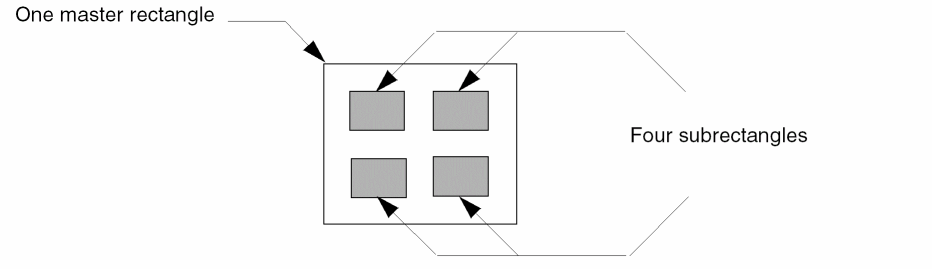
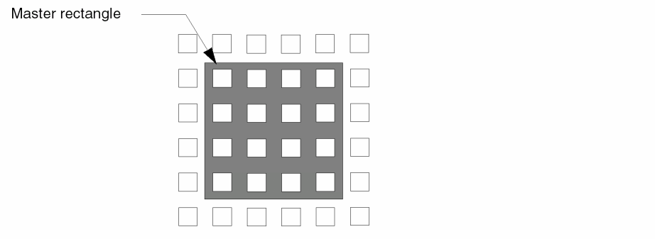
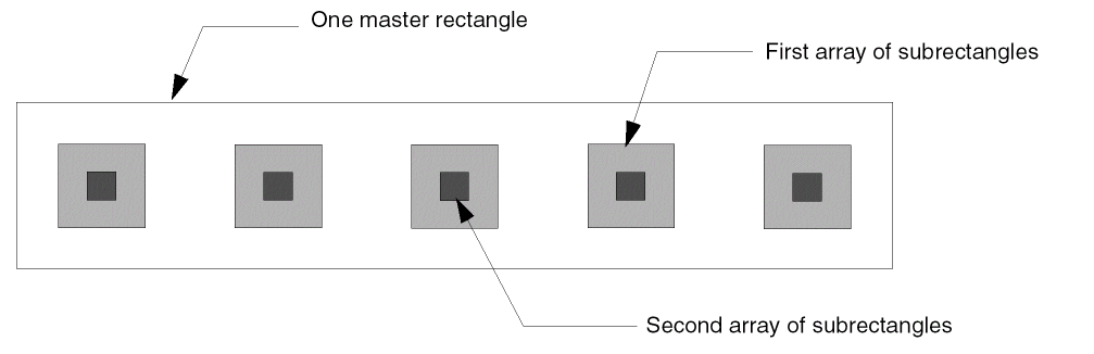
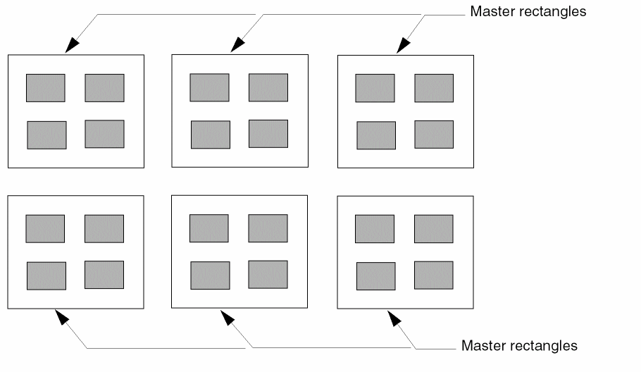
Multipart Rectangles
A multipart rectangle (MPR) is a single object composed of multiple parts on the same or on different layers. The parts consist of one or more named master rectangles and one or more arrays of unnamed subrectangles. Each named master rectangle is a separate object with ROD attributes, created at level zero in the hierarchy. Each unnamed subrectangle is an ordinary database shape with no ROD attributes, created at level zero in the hierarchy.
You create MPRs with the rodCreatePath function. For example, you might create a single master rectangle with a two-dimensional array containing four subrectangles,
a single master rectangle overlapped by rows and columns of subrectangles (a two-dimensional array),
one master rectangle with two one-dimensional arrays containing five subrectangles each,
or six master rectangles and a two-dimensional array containing four subrectangles. The array of subrectangles repeats for each master rectangle (you define the array once).
Connectivity for Multipart Rectangles
You can create connectivity for all master rectangles and/or for any array of subrectangles by associating them with a specific terminal and net. You can also make all master rectangles into pins and/or all subrectangles of any array into pins.
An array of unnamed subrectangles is treated as a single shape. However, you can get a list of the database IDs for the individual subrectangles within an array by using the ROD object ID for the multipart path with the database access operator (~>) and the attribute name subShapes. If you use the database ID to change connectivity information (such as terminal name) for one or more individual subrectangles, your change is propagated to all of the subrectangles in the array of subrectangles. For more information, see Accessing ROD Object Attributes.
System-Defined Handles for Multipart Paths
For multipart rectangles, the system defines handles based on the points of the master rectangles only. Subrectangles are ordinary database shapes with no ROD attributes. The handles for master rectangles are the same as for any ROD rectangle.
For more information, see System-Defined Handles.
Multipart Rectangles as ROD Objects
When you create multipart rectangles, the system creates a rectangle and ROD object information for each master rectangle, including its name and database ID. The ROD object is identified by a ROD object ID. The database IDs for a multipart rectangle identify the master rectangles. Subrectangles are regular, unnamed database shapes without any ROD attributes.
For a detailed description of ROD objects and ROD object IDs, see About ROD Objects and ROD Object IDs.
Creating a Multipart Rectangle from Other Objects
You can create a new master rectangle without specifying points by using one or more of the following as source objects: an instance or any ROD object.
For a detailed overview about creating objects from other objects, see Creating Objects from Objects.
Editing Multipart Rectangles
For a summary of how the Virtuoso® layout editor commands work with ROD objects, see Appendix E, “How Virtuoso Layout Editor Works with ROD Objects”. Using commands that are not fully supported for ROD objects could cause the objects to lose the ROD information associated with them, changing the objects into ordinary, unnamed shapes.
When you select any part of a master rectangle or its associated subrectangles, the whole master rectangle and all associated subrectangles are selected. The master rectangle is highlighted on the current selection layer, while the arrays of subrectangles are highlighted on different layers to let you see which part is the master and which parts are arrays of subrectangles.
When you modify a multipart rectangle with the layout editor, changes to a master rectangle also affect all of its associated subrectangles; you cannot edit or copy an array of subrectangles or individual subrectangles.
Stretching Multipart Rectangles
You can stretch the edges and/or corners of a master rectangle of a multipart rectangle in the same way you stretch regular rectangles, by clicking on an edge or vertex, then clicking in a new location. The system regenerates the arrays of subrectangles associated with the stretched master rectangle, changing the number of subrectangles in each array; the shape of the subrectangles does not change. You cannot stretch a master rectangle separately from its subrectangles, nor can you stretch subrectangles separately from their master rectangle.
The way that subrectangles regenerate depends on how the multipart rectangle was defined with the rodCreateRect function. For information about defining multipart rectangles, see rodCreateRect.
Multipart Paths
A multipart path (MPP) is a single ROD object consisting of one or more parts at level zero in the hierarchy on the same or on different layers. You can create one-part paths, simple multipart paths, or complex multipart paths such as guard rings, transistors, buses, and shielded paths. This section provides an overview of multipart path concepts.
You can create MPPs in the ways listed below.
This section provides an overview of multipart path concepts.
-
With the Virtuoso layout editor Create Multipart Path command
For information about using the Create Multipart Path command, see “Creating and Editing Multipart Paths” in the Virtuoso Layout Suite L User Guide. - For guard rings, with the Quick Cell graphical user interface
- With the SKILL function rodCreatePath
-
By editing the ASCII version of your technology file
For information about editing your technology file, see “multipartPathTemplates” in the Virtuoso Technology File Data: ASCII Files Reference Manual.
You create a ROD path by specifying a point list for the master path or by specifying one or more named objects as a source for the points of the master path.
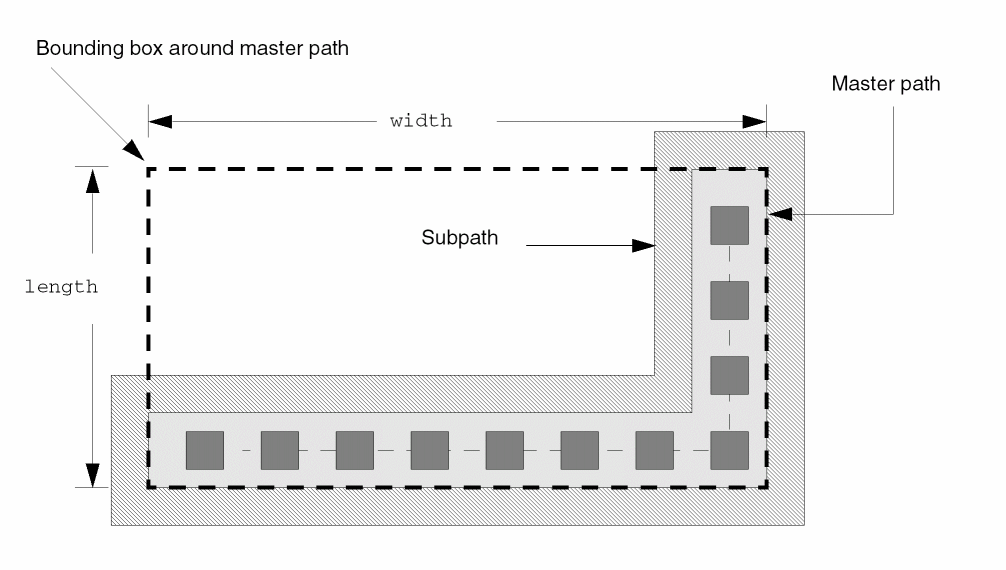
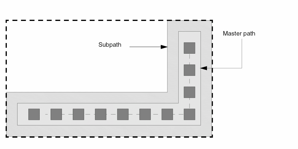
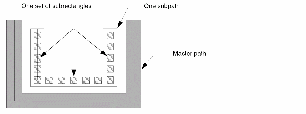
A multipart path consists of a single master path and one or more subparts. The master path is an ordinary path; however, it is the defining part of a multipart path; all subparts are based on the master path. The subparts can be any combination of offset subpaths, enclosure subpaths, and sets of subrectangles.
Types of Subparts
- An offset subpath is a path that is coincident with an edge of the master path, overlapping the master path, or separated from the master path.
- An enclosure subpath is a path with its centerline on the centerline of the master path and is usually narrower or wider than the master path. The system calculates its width using the width of the master path and a positive or negative enclosure value.
- A set of subrectangles consists of one or more subrectangles that are coincident with an edge of the master path, overlapping the master path, or separated from the master path
You can create any number of subparts. All subparts exist in relation to and depend on the master path. A subrectangle in a set of subrectangles is not an individual shape; it is part of that specific set of subrectangles. You cannot select or edit individual subrectangles.
For example, the multipart path shown below has one subpath and one set of subrectangles. Both the subpath and the set of subrectangles are offset from the master path.
Master Paths
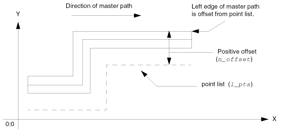
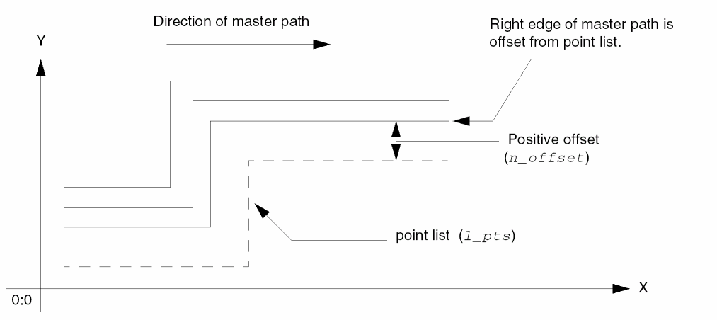
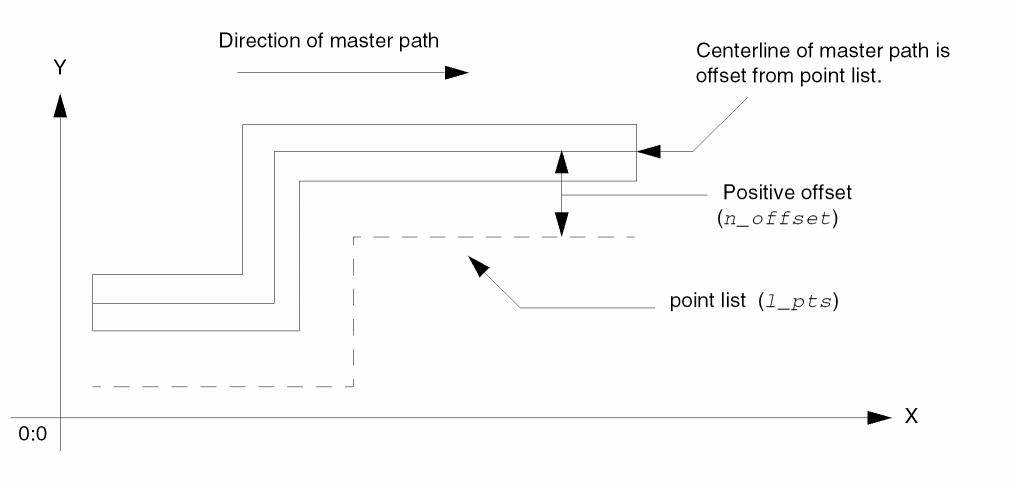
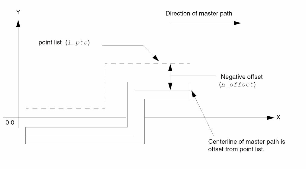
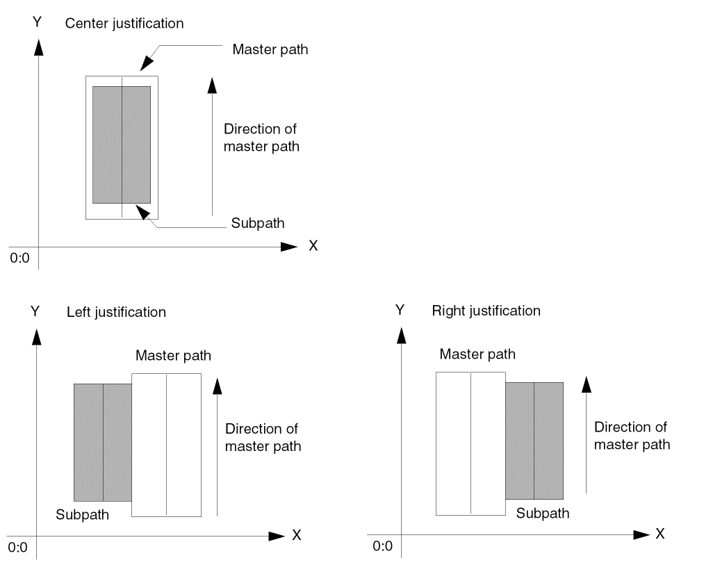
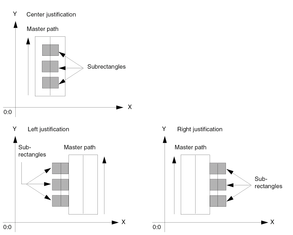
You create the master path for a multipart path by specifying a list of points (point list). To control where the master path appears in relation to the point list, you can specify justification and an offset.
- Offset specifies the distance between the master path and the points in the point list.
- Justification specifies whether to offset the centerline, left edge, or right edge of the master path from the point list.
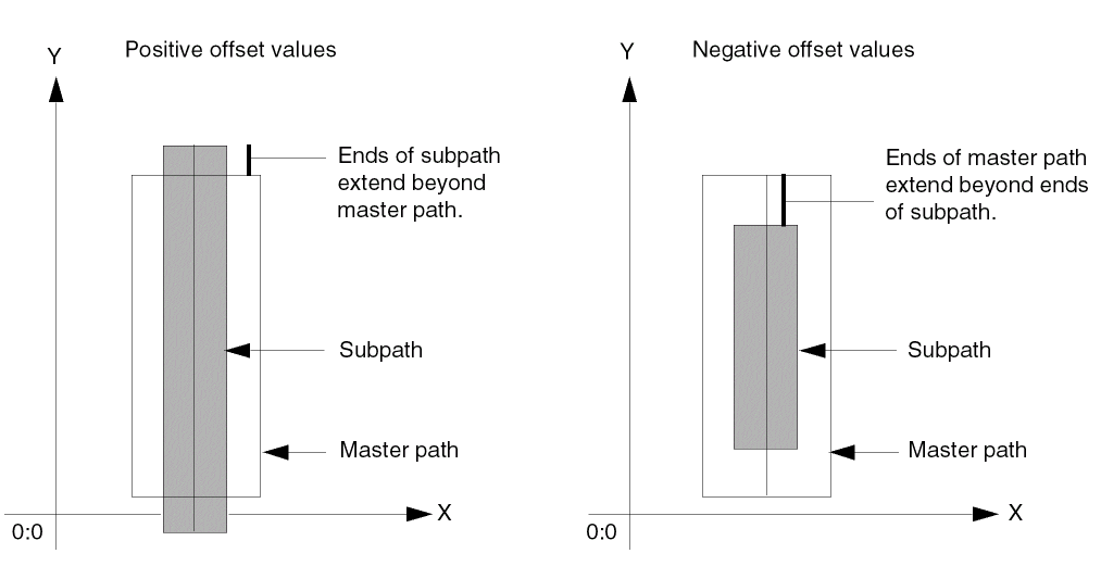
Both offset and justification are relative to the direction of the master path. The direction of the master path is determined by the sequence in which you specify its points.
Position of Master Path in Cellview
The location of the master path in a layout cellview window in relation to the points in the point list depends on whether the offset value is positive or negative and on the direction of each segment in the point list, as shown in Table 1-2.
Examples of Offsetting the Master Path
The following examples show offset master paths.
Master Path with Positive Offset, Left Justification
When the offset is positive with left justification, the left edge of the master path is offset from the point list, creating a master path on the left side of the point list.
Master Path with Positive Offset, Right Justification
When the offset is positive with right justification, the right edge of the master path is offset from the point list, creating a master path on the left side of the point list.
Master Path with Positive Offset and Center Justification
When the offset is positive with center justification, the centerline of the master path is offset to the left of the point list, in relation to the direction of the point list.
When you specify a negative value for offset, the system offsets the master path to the right of the point list, using the left edge, right edge, or centerline of the master path, as specified by the justification.
Master Path with Negative Offset and Center Justification
When the offset is negative with center justification, the centerline of the master path is offset to the right of the point list, in relation to the direction of the point list.
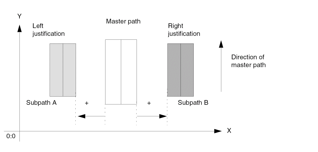
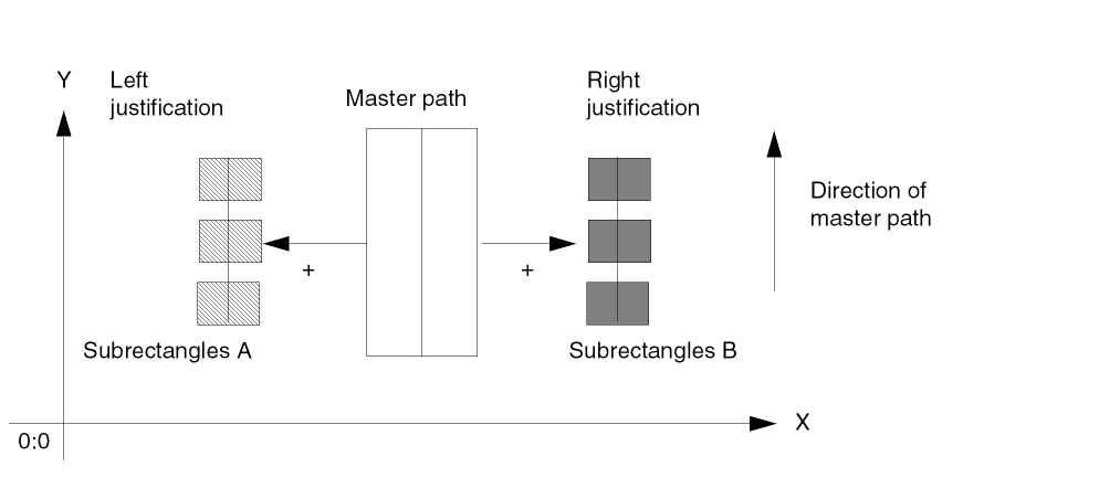
Offset Subpaths
You can create an offset subpath that is coincident with an edge of the master path, on the left or right side of the master path, or overlapping the master path. You can specify the width of an offset subpath or let it default to the minWidth rule for the subpath layer from the technology file. Offset subpaths inherit the same type of end as specified for the master path.
You determine where to create an offset subpath in relation to the master path by specifying the separation and justification. Both separation and justification are relative to the direction of the master path. The direction of the master path is determined by the sequence in which you specify its points.
- Separation specifies the distance between the offset subpath and the master path.
-
Justification specifies whether to separate edges or centerlines as follows:
-
leftseparates the right edge of the subpath from the left edge of the master path. -
rightseparates the left edge of the subpath from the right edge of the master path. -
centerseparates the centerline of the subpath from the centerline of the master path.centerjustification for subpaths follows the same rules ascenterjustification for offset master paths.
-
Specifying Separation and Justification
The location of an offset subpath in relation to the master path depends on the values of separation and justification, in relation to the direction of the master path. To create a subpath
-
With its centerline on the master path centerline, specify
centerjustification with zero separation -
Coincident with the left or right edge of the master path, specify
leftorrightjustification, respectively, and let separation default to zero -
With its centerline separated from the master path centerline, specify
centerjustification with a positive or negative separation -
To the left or right of the master path, specify
leftorrightjustification, respectively, with a positive separation -
Overlapping the left or right edge of the master path, specify
leftorrightjustification, respectively, with a small negative separation
For a summary of how to specify separation and justification for offset subpaths, see Table 1-3.
Examples of Offset Subpaths
The following examples show offset subpaths in relation to a master path.
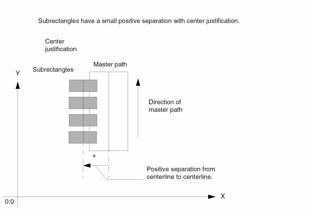
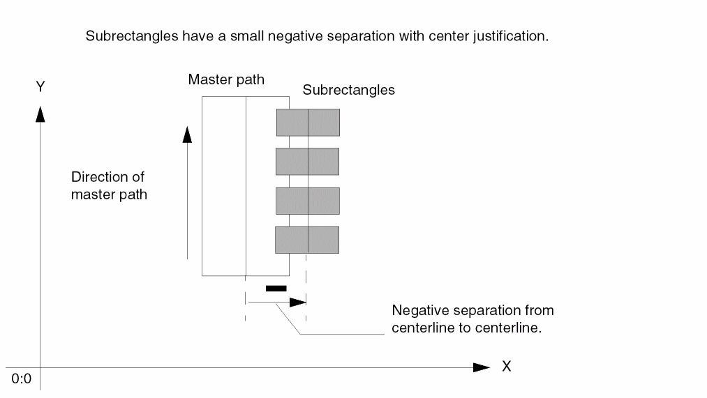
Zero Separation for Offset Subpaths
When the separation value is zero (0), the offset subpath centerline is on the master path centerline, or the subpath is coincident with an edge of the master path, depending on the justification, as shown below:
Positive Separation for Offset Subpaths
When the separation value is positive, the offset subpath is on the left or right side of the master path, depending on the justification.
For example, both Subpath A and Subpath B have positive separations.
- Subpath A has left justification, so the left edge the master path is separated from the right edge of Subpath A.
-
Subpath B has right justification, so the right edge of the master path is separated from the left edge of Subpath B.
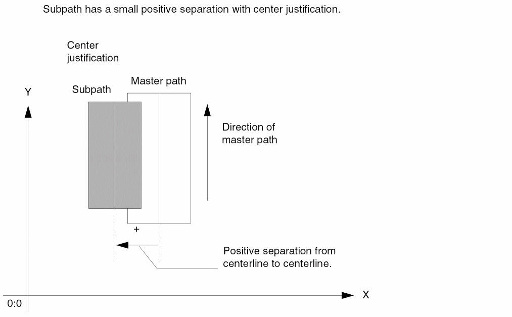
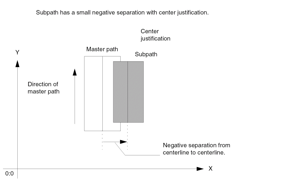
The following example shows a small, positive separation value with center justification, creating a subpath that overlaps the left edge of the master path. The subpath centerline is offset from the master path centerline.
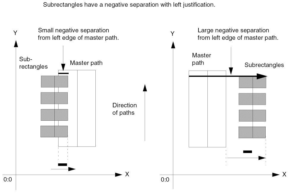
Negative Separation for Offset Subpaths
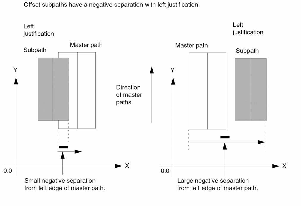
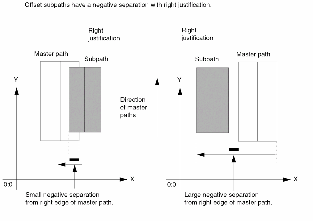
When the separation value is negative, the offset subpath either overlaps the master path or is created on the side of the master path opposite the side specified by justification, relative to the direction of the master path.
The examples below show both small and large negative separation values with left justification. The left edge of the master path is separated from the right edge of the offset subpath.
The examples below show both small and large negative separation values with right justification. The right edge of the master path is separated from the left edge of the offset subpath.
The following example shows a small, negative separation with center justification, creating an offset subpath overlapping the right side of the master path. The subpath centerline is offset from the master path centerline.
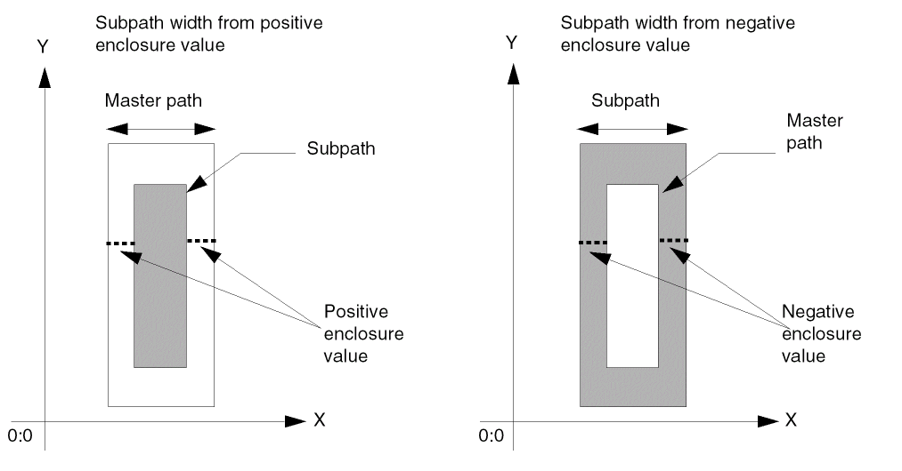
Enclosure Subpaths
You create an enclosure subpath with its centerline on the centerline of the master path and its width calculated using the width of the master path plus a positive or negative enclosure value. The enclosure determines by how much the subpath is enclosed by the master path or by how much the master path is enclosed by the subpath.
You can specify the enclosure for the subpath or let it default to the minEnclosure rule from the technology file for the master path layer to the subpath layer. minEnclosure defines the minimum enclosure for the master path layer in relation to the subpath layer. Enclosure subpaths inherit the same type of ends as specified for the master path.
To define enclosure for the ends of the subpath, you can specify offsets or let the system default to the value of the n_enclosure argument.
Examples of Enclosure Subpaths
To calculate the width of an enclosure subpath, the system subtracts two times the enclosure value from the width of the master path:
Width of Enclosure Subpath = Width of Master Path - (2 * Enclosure Value)
Therefore, a positive enclosure value creates a subpath that is narrower than the master path, and a negative enclosure value creates a subpath that is wider than the master path. The centerlines are always coincident.
The following examples show enclosure subpaths with positive and negative enclosure values.
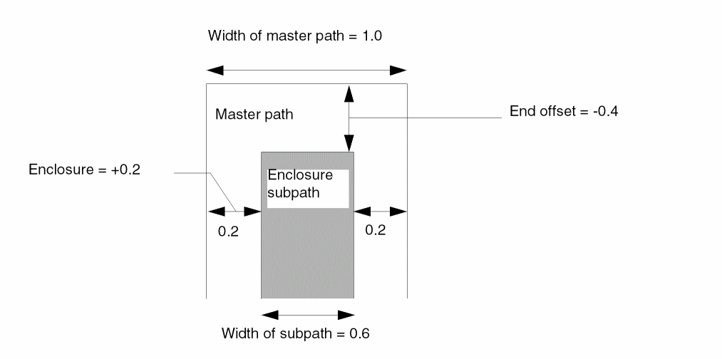
The following example shows a master path with a width of 1.0 and an enclosure subpath with the enclosure value of a positive 0.2. Both ends of the subpath are offset by a negative 0.4.
Therefore, the master path encloses the subpath by 0.2 on each side, making the width of subpath 0.6. The end of the master path encloses the subpath by a negative 0.4.
Sets of Subrectangles
You can create a set of subrectangles in relation to the centerline of any master path. The set can contain one or more subrectangles.
You can specify the width and length of the subrectangles or let them default to the minWidth rule for the subrectangle layer from the technology file. You can offset the centerline of the subrectangles from the master path centerline, and you can offset the edge of the first and last subrectangles from the ends of the master path. You can also specify the offset of the first and last subrectangle in a segment. The system places subrectangles on grid.
You can create connectivity for a set of subrectangles. When you specify that a set of subrectangles is a pin, each rectangle in the set becomes a pin. In the layout editor, a set of subrectangles is treated as a single shape. You cannot edit or select individual subrectangles.
Although a set of subrectangles is treated as a single shape, you can get a list of the database IDs for the individual subrectangles in the set by using the ROD object ID for the multipart path with the database access operator (~>) and the attribute name subShapes. If you use the database ID to change connectivity information (such as terminal name) for one or more individual subrectangles, your change is applied to the individual subrectangles immediately, and propagated to all of the subrectangles in the set of subrectangles when the MPP is modified in any way (such as moved). For more information, see Accessing ROD Object Attributes.
Specifying Separation and Justification
The location of a set of subrectangles in relation to the master path depends on the values of separation and justification, in relation to the direction of the master path, just as it does for offset subpaths. The system places subrectangles on grid, as close to the specified separation as possible. To create a set of subrectangles
-
With the center of the width of the subrectangles on the master path centerline, specify
centerjustification with zero separation -
Coincident with the left or right edge of the master path, specify
leftorrightjustification, respectively, and let separation default to zero -
With the center of the width of the subrectangles separated from the master path centerline, specify
centerjustification with a positive or negative separation -
To the left or right of the master path, specify
leftorrightjustification, respectively, with a positive separation -
Overlapping the left or right edge of the master path, specify
leftorrightjustification, respectively, with a negative separation
For a summary of how to specify separation and justification for sets of subrectangles, see Table 1-4.
When you specify connectivity for a set of subrectangles, the connectivity applies to all rectangles in the set. Similarly, when you specify that a set of subrectangles is a pin, all rectangles in the set become pins.
For a detailed description of how the system creates subrectangles, see
Examples of Sets of Subrectangles
The following examples show sets of subrectangles in relation to a master path.
Zero Separation for a Set of Subrectangles
When the separation value is zero (0), the centerline of the subrectangles is on the master path centerline or the subrectangles are coincident with an edge of the master path, depending on the justification, as shown below:
Positive Separation for a Set of Subrectangles
When the separation value is positive, the subrectangles overlap the master path or are on the left or right side of the master path, depending on the size of the separation value and on the justification.
For example, both Subrectangles A and Subrectangles B have positive separations.
- Subrectangles A has left justification, so the left edge of the master path is separated from the right edge of Subrectangles A.
-
Subrectangles B has right justification, so the right edge of the master path is separated from the left edge of Subrectangles B.
The following example shows subrectangles that overlap the left edge of the master path, created with a small, positive separation value and center justification. The subpath centerline is on the left side of the master path centerline.
Negative Separation for a Set of Subrectangles
When the separation value is negative, the set of subrectangles either overlaps the master path or is created on the side of the master path opposite the side specified by justification, relative to the direction of the master path.
The examples below show both small and large negative separation values with left justification. The left edge of the master path is separated from the right edge of the set of subrectangles.
The following example shows subrectangles that overlap the right edge of the master path, created with a small, negative separation and center justification. The master path centerline is separated from the subrectangle centerline.
Ends of Paths and Subrectangles
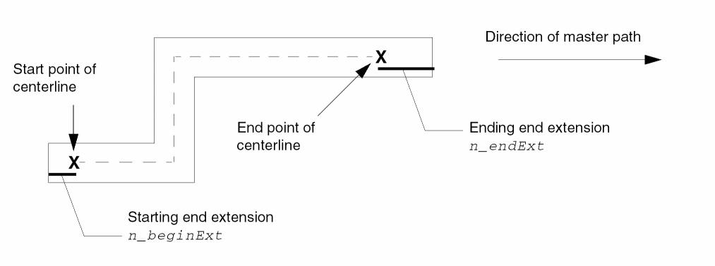
You can specify extensions for each end of a master path to make the end extend beyond the start and/or end point of the master path centerline. To specify end extensions for a master path, use the n_beginExt and n_endExt arguments, with the master path S_endType argument set to variable.
All subparts inherit the end extensions of the master path.
Offsetting the Ends of Subpaths and Subrectangles
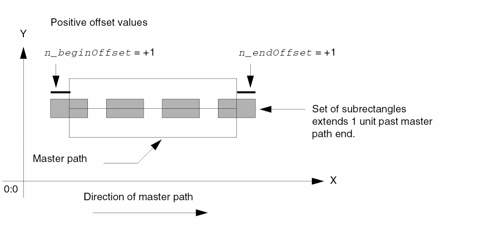
You can create a subpath or set of subrectangles that is longer or shorter than the master path. You do this by specifying the n_beginOffset and n_endOffset arguments to offset the ends of the subpath or subrectangle from the ends of the master path. With or without an offset, subpaths and subrectangles are generated starting at the first edge of the master path.
If you do not specify offsets, the system creates the ends as follows:
- For offset subpaths and sets of subrectangles, the end offsets default to zero, so their ends are coincident with the ends of the master path.
-
For enclosure subpaths
- If you specify only n_beginOffset, n_endOffset defaults to n_beginOffset; if you specify only n_endOffset, n_beginOffset defaults to n_endOffset.
- If you do not specify an offset but do specify an enclosure, the offsets default to the negative of the enclosure.
-
If you specify neither an offset nor an enclosure, the system subtracts the value of the
minEnclosurerule (from the technology file for master path layer to subpath layer) from the ends of the master path to calculate the offset for the ends of the enclosure subpath. If theminEnclosurerule is not defined in the technology file, the system reports an error.
Examples of Ends of Subpaths and Subrectangles
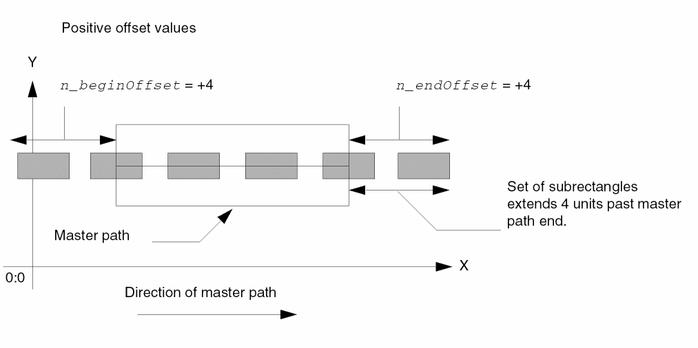
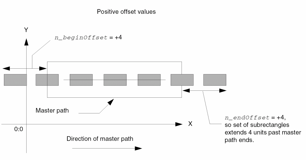
When offsets of the ends are positive, the subpath extends beyond the master path. When negative, the master path extends beyond the subpath.
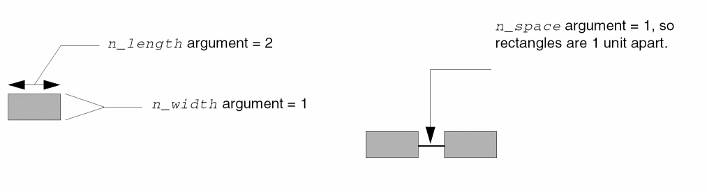
In the following examples of sets of subrectangles, the rectangles are 1 unit wide and 2 units long, spaced 1 unit apart.
Positive Offsets for Ends of Subrectangles
This example shows small positive offsets for the ends of a set of subrectangles.
This example shows larger positive offsets for the ends of a set of subrectangles.
The following example shows positive offset values for the ends of a set of rectangles when the master path has extended ends.
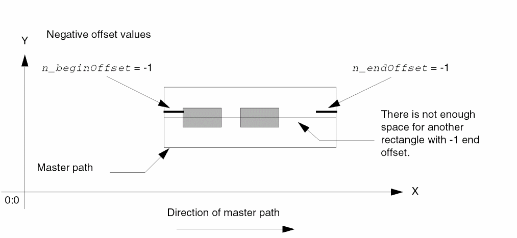
Negative Offsets for Ends of Subrectangles
This example shows negative offsets for the ends of a set of subrectangles.
Keeping Subrectangles Out of the Corners of Subrectangle Subpaths
If you want to keep the corners of the segments of a subrectangle subpath free of subrectangles, you can do so by specifying the n_beginSegOffset and n_endSegOffset arguments. For a detailed description, see
Making Paths Choppable
You can define one or more parts of a multipart path as choppable. When you define the master path as choppable, then all of its subpaths and subrectangles must be choppable also. When you define the master path is not choppable, you can define each subpath or set of subrectangles as choppable or not choppable.
When an object is choppable, you can use the Virtuoso layout editor Chop command or the rodAddMPPChopHole function to separate it into two or more paths; the results are the same with either method.
For an overview of how chopping affects multipart paths, see Chopping Multipart Paths.
Connectivity for Multipart Paths
You can create connectivity for any or all parts in a multipart path by associating them with a specific terminal and net. You can also make one or more parts into pins. When you specify that a master path or a subpath is a pin, the whole path becomes a pin. When you specify that a set of subrectangles is a pin, each rectangle in that set of subrectangles becomes a pin.
System-Defined Handles for Multipart Paths
The system defines handles for multipart paths based on the points of the master path only. For more information, see System-Defined Handles.
Multipart Paths as ROD Objects
When you create a multipart path, the system creates both a path and a ROD object containing information associated with the path, including its name and database ID. The ROD object is identified by a ROD object ID. The database ID for a multipart path identifies the master path.
For a detailed description of ROD objects and ROD object IDs, see About ROD Objects and ROD Object IDs.
Creating a Path from Other Objects
You can create a new path from one or more of the following: an instance or any ROD object without specifying the points for the path.
For a detailed overview about creating objects from other objects, see Creating Objects from Objects.
Editing Multipart Paths
For a summary of how the Virtuoso layout editor commands work with ROD objects, see Appendix E, “How Virtuoso Layout Editor Works with ROD Objects.” Using commands that are not fully supported for ROD objects could cause the objects to lose the ROD information associated with them, changing the objects into ordinary, unnamed shapes.
When you select any part of a multipart path in a layout cellview window, all shapes in the multipart path are selected and highlighted. When you modify a multipart path with the Virtuoso layout editor, changes to the master path also affect all of its subparts; you cannot edit or copy an individual subpart. For example:
- Chopping a multipart path affects all choppable parts of the multipart path.
- Stretching a segment of a multipart path stretches the segment subpaths and, for orthogonal segments, regenerates subrectangles. The number of subrectangles in a subpath changes; the shape of the subrectangles does not change.
When you edit a multipart path that has subrectangles, the system regenerates all subrectangles that occur in orthogonal segments (segments parallel or perpendicular to an axis). The system does not generate or regenerate subrectangles in nonorthogonal segments.
Chopping Multipart Paths
You can define one or more parts of a multipart path as choppable.
- When you define the master path as choppable, then all of its subpaths and subrectangles must be choppable also.
- When you define the master path is not choppable, you can define each subpath or set of subrectangles as choppable or not choppable.
- If the master path is choppable, you can chop the whole multipart path into two or more separate multipart paths by chopping all the way through the master path at 90 degrees.
-
If the master path is not choppable, you can chop all subparts that are specified as choppable by chopping all the way through the master path at 90 degrees. All choppable subparts are chopped where you chop over the master path.
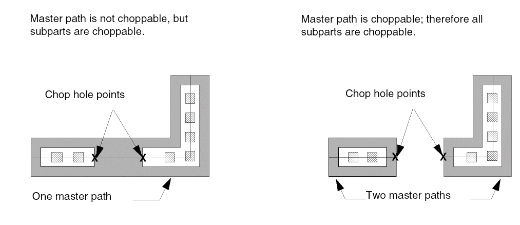
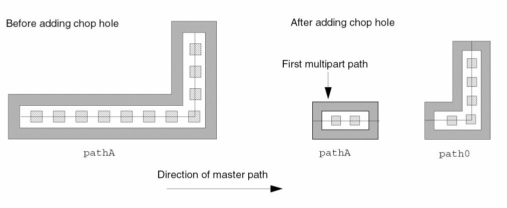
When you chop a choppable master path, the system assigns the name of the original multipart path to the first new multipart path, where “first” is relative to the direction of the master path.
The system assigns unique names to the other new multipart paths, starting with path0, path1, and so on, as shown below.
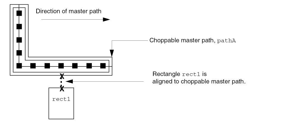
Chopping Multipart Paths That Have Alignments
When you chop through the (choppable) master path of a multipart path, alignments to other objects are lost. The following example shows what happens to an aligned object after cutting away a section of a choppable master path named pathA.
When you use the cutter to chop out part of the master path like this,
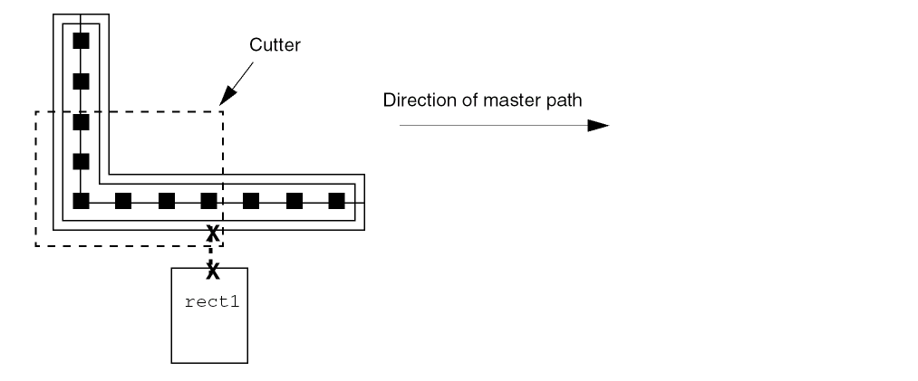
the result is two new, shorter multipart paths, neither of which are aligned to rect1.
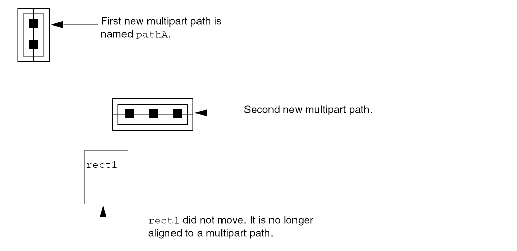
The system keeps the name pathA with the first new multipart path and assigns a unique name in the format of pathn to the second new multipart path.
For more information about how the layout editor Chop command affects multipart paths, see
Stretching Multipart Paths
You can stretch the ends, segments, and/or corners of a multipart path in the same way you stretch single-part paths; however, the master path and its subparts stretch together. You cannot stretch the master path separately from its subparts, nor can you stretch subparts separately from the master path.
In the example below, when you stretch the bottom segment downward, all parts of the multipart path stretch together. The system regenerates subrectangles to fill the orthogonal segments affected by the stretch.
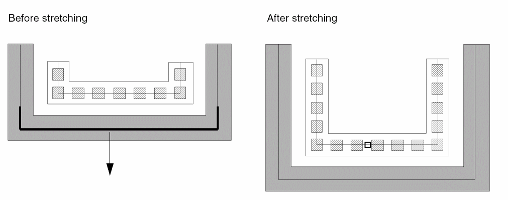
You can select and stretch the chopped ends of subpaths. When the multipart path contains sets of subrectangles, the system regenerates subrectangles along orthogonal segments only.
For more information about stretching multipart paths, see
Creating Objects from Objects
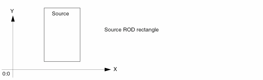
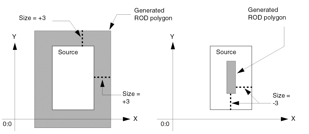
Using the rodCreateRect, rodCreatePolygon, or rodCreatePath function, you can create a new rectangle, polygon, or path from an instance or ROD object or from multiple objects. The existing objects are referred to as source objects, and the new object is referred to as the generated object.
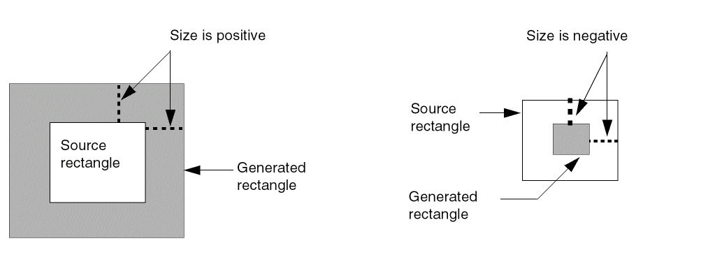
When the source is a single object, you specify the difference between the size of the source object and the size of the generated object. For example, from a source rectangle, the system uses a positive size to generate an new, larger rectangle, and a negative size to generate a new, smaller rectangle.
When the source is more than one object, you specify the difference between a bounding box around all of the objects and the size of the generated object.
If you specify a negative size that is too small for generating a new object, the system reports an error. For example, when the source object is a path and you specify a negative size, its absolute value cannot be equal to or greater than half of the width of the source path. If the source path has a width of 4, you cannot generate a new path by specifying a size of -2. Applying -2 to the perimeter of the source path would produce a path with a width that is less than or equal to zero.
Creating a Rectangle from Another Object
You can create a new rectangle from one or more ROD objects. The system computes the point list for the new rectangle by applying the size you specify to the bounding box around the source object(s). When the source object is also a rectangle, its bounding box is the same as its shape.
The following sections show examples of creating rectangles from a variety of shapes.
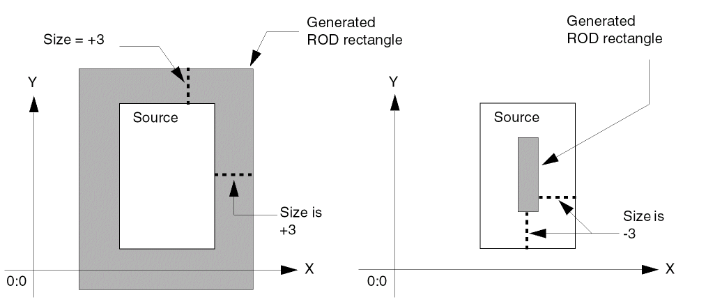
Creating a Rectangle from a Rectangle
When the source object is a rectangle,
and you specify the size as +3, the system generates a new, larger rectangle. When you specify the size as -3, the system generates a new, smaller rectangle.
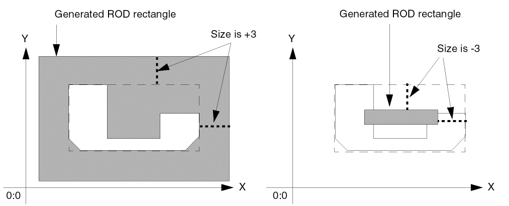
Creating a Rectangle from a Polygon
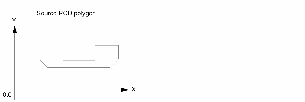
When the source object is a polygon,
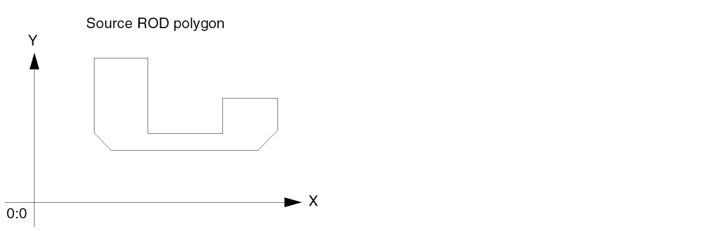
and you specify the size as +3, the system computes a bounding box around the polygon and generates a new rectangle that is larger than the bounding box. When you specify the size as -3, the system generates a new rectangle that is smaller than the bounding box.
Creating a Rectangle from a Path
When the source object is a path,
and you specify the size as +3, the system computes a bounding box for the path and generates a new rectangle that is larger than the bounding box. When the size is -3, the system generates a rectangle that is smaller than the bounding box.
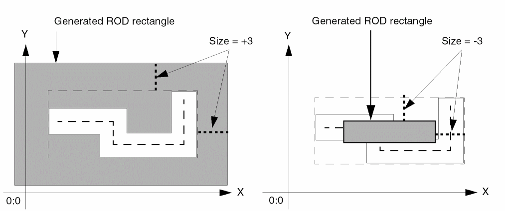
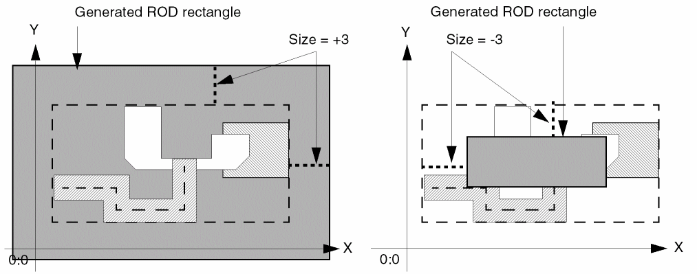
Creating a Rectangle from Multiple Objects
When there are several source objects,
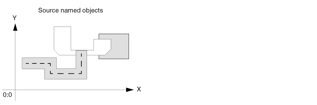
and you specify the size as +3, the system computes a bounding box around all of the objects and generates a new rectangle that is larger than the bounding box. When you specify the size as -3, the system generates a rectangle that is smaller than the bounding box.
Creating a Polygon from Another Object
You can create a new polygon from one or more instances and/or ROD objects. The system computes the point list for the new polygon by applying the size you specify. If you specify a size that is too small for generating a new polygon, the system reports an error.
The following sections show examples of creating polygons from a variety of shapes.
Creating a Polygon from a Rectangle
When the source object is a rectangle,
and you specify the size as +3, the system generates a new polygon that is larger than the bounding box. When you specify the size as -3, the system generates a new polygon that is smaller than the bounding box.
Creating a Polygon from a Polygon
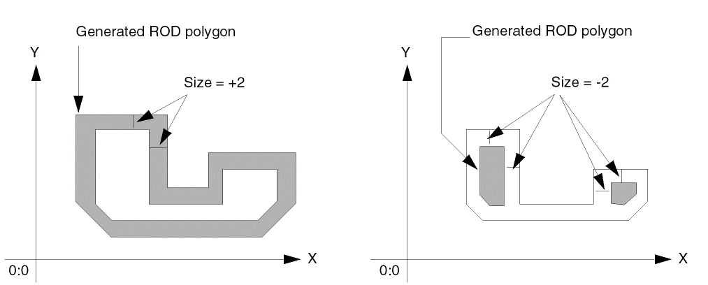
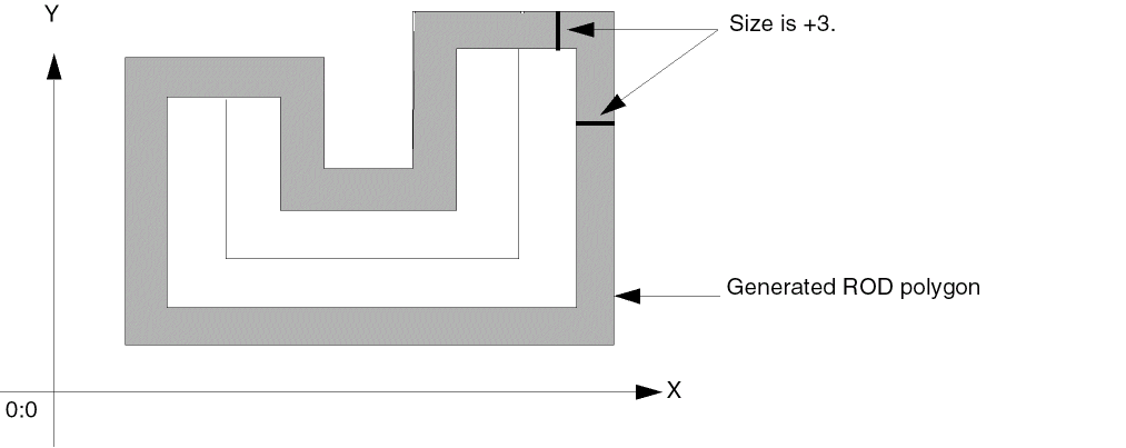
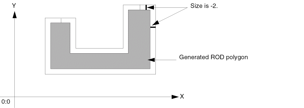
When the source object is a polygon,
and you specify the size as +2, the system generates a new, larger polygon. When you specify the size as -2, the system generates two new, smaller polygons that are not connected, because -2 is smaller than the narrowest part of the source polygon.
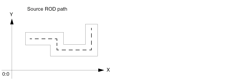
Creating a Polygon from a Path
When the source object is a path,
and you specify the size as +3, the system generates a new polygon that is larger than the path.
When you specify the size as -2, the system generates a new polygon that is smaller than the path.
Creating a Polygon from Multiple Objects
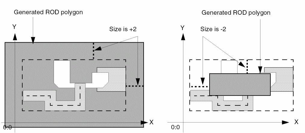
When there are several source objects,
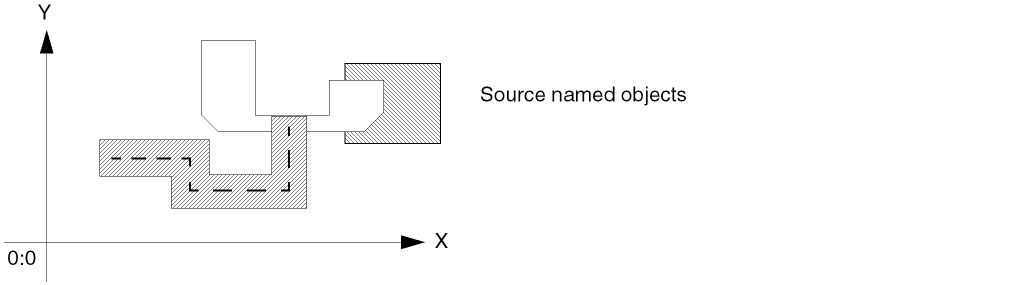
and specify the size as +2, the system computes a bounding box around all of the objects and generates a new polygon that is larger than the bounding box. When you specify the size as -2, the system generates a new polygon that is smaller than the bounding box.
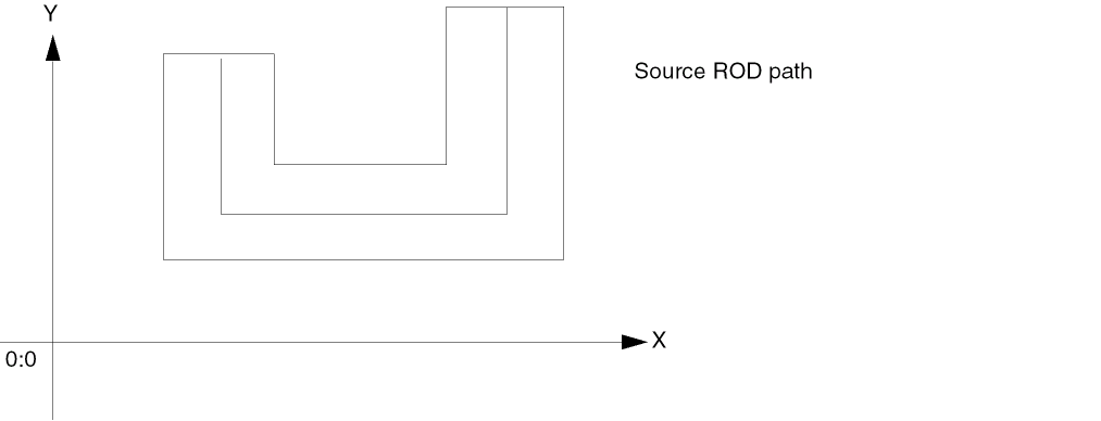
Creating a Path from Another Object
You can create a new path from any ROD object or from multiple ROD objects. You can specify a size differential and also a starting and ending point or let the new path default to a self-abutting ring. When the source object is a path, the system applies the size differential to its perimeter.
When generating a path, the system does the following:
-
Computes the point list for the new path by applying the size as the distance between the centerline of the generated master path and
- For a single source object, the perimeter of the source object.
- For multiple source objects, the bounding box around all of the source objects.
If you specify a negative size that is too small for generating a new path, the system reports an error. For example, when the source object is a path, the absolute value of a negative size cannot be greater than or equal to half of the width of the source path. - Starts the path at the point closest to the starting point of the source object. For rectangles, instances, and multiple source objects, the generated path always starts relative to the lower-left corner of the bounding box around the source object(s).
-
Creates the direction of the new path as follows:
- When the source object is a single rectangle, instance, or path, in a clockwise direction.
- When there are multiple source objects, in a clockwise direction.
- When the source object is a polygon, in the direction in which the polygon was created. For example, when the source polygon was created in a counter-clockwise direction, the system creates the path in a counter-clockwise direction.
The following sections show examples of creating paths from a variety of shapes.
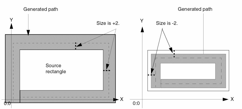
Creating a Path from a Rectangle
When the source object is a rectangle,
and you specify the size as +2, the system generates a new, larger path. When you specify the size as -2, the system generates a new, smaller path.
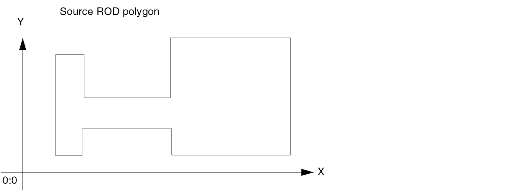
Creating a Path from a Polygon
When the source object is a polygon,
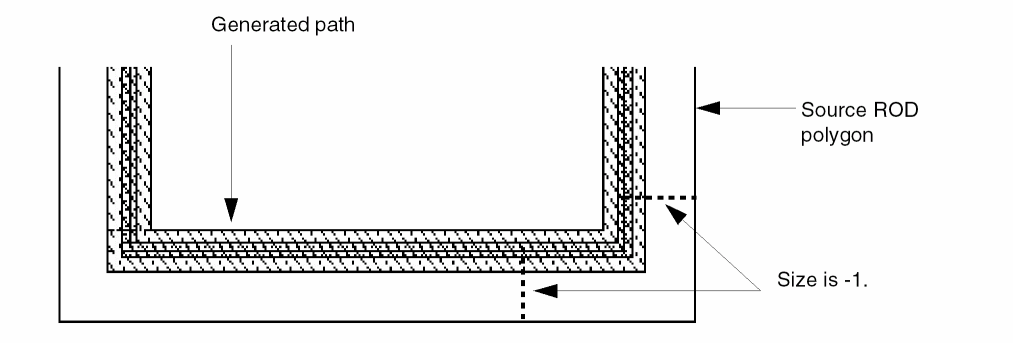
and you specify the size as -1, the system generates a new path inside the perimeter of the polygon.
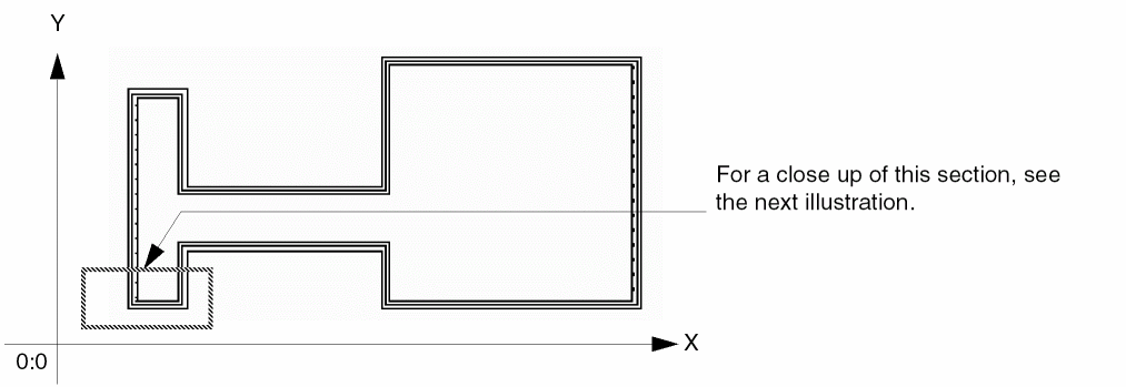
Here is a close up of the bottom left side of the polygon and new path:
When you specify a small enough size, in this case -5, the system generates a new path only inside the perimeter of the right side of this polygon.
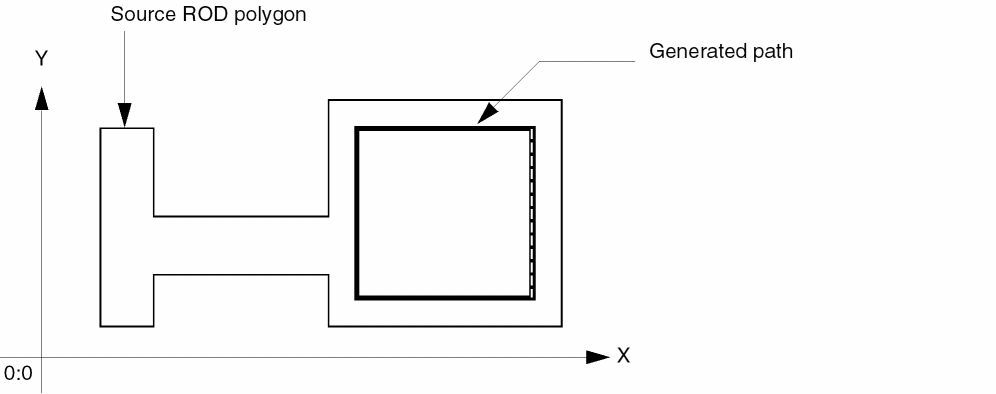
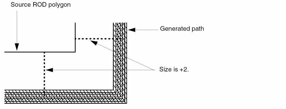
When you specify the size as +2, the system generates a new path outside the perimeter of the polygon.
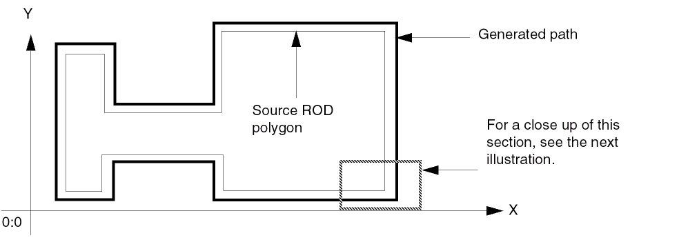
Here is a close up of the bottom right corner of the polygon and new path:
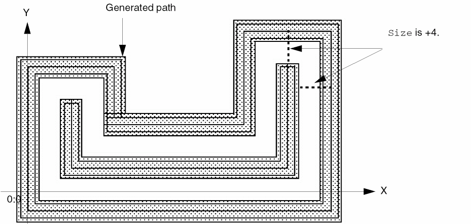
Creating a Path from a Path
When the source object is a path with a width of 3,
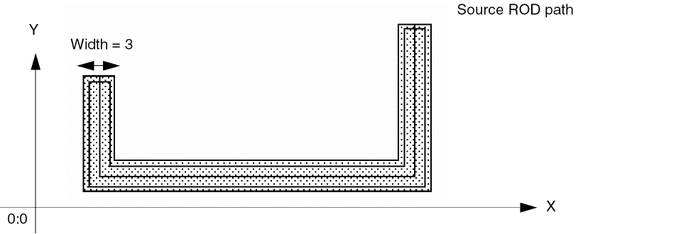
and you specify the size as +4, the system generates a new path that is larger than the source path.
Using the source path with a width of 3 from the previous example, the system would not create a path with a size of -1.5 because the absolute value of -1.5 is greater than or equal to half of the width of the source path. The system cannot create a path unless its width is greater than zero.
Here is an example of specifying a negative size to generate a new path from an existing path. When the source path has a width of 6,
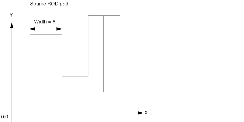
and you specify the size as -2, the system generates a new path that is smaller than the source path.
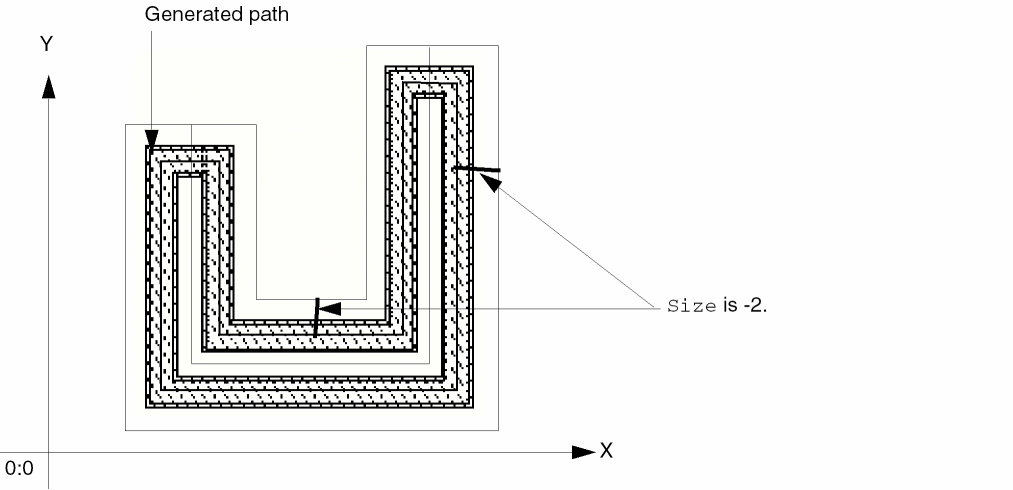
Creating a Path from Multiple Objects
When you specify multiple source objects,
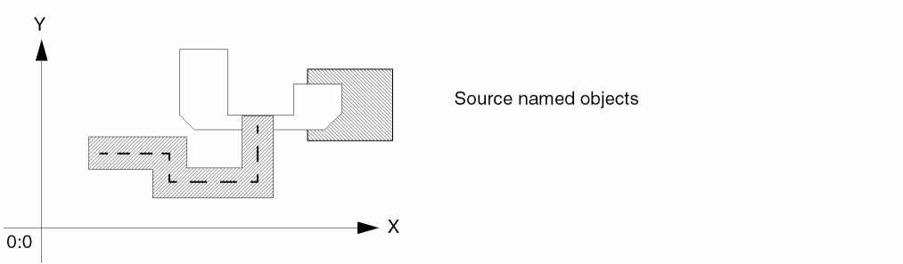
the generated path forms a ring with the centerline of the master path offset from the bounding box by the size you specify. By default, the path has four segments. The new path is longer or shorter depending on whether you specify a positive or negative size.
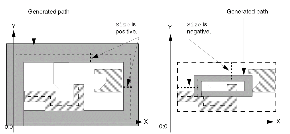
Connectivity
When you use a ROD function to create a shape, such as a rectangle or path, you can specify connectivity for the shape by associating it with a specific terminal and net. You can also make the shape into a pin.
To specify connectivity for an object, you must use the ROD connectivity arguments. You can do this within a rodCreate function, such as rodCreateRect, by specifying values for the terminal name, terminal I/O type, and pin connectivity arguments.
For a multipart path, you can create connectivity for any or all parts of the multipart path: the master path, subpaths and/or subrectangles. When you make the master path into a pin, the whole master path becomes a pin; when you make a subpath into a pin, the whole subpath becomes a pin; and when you make a set of subrectangles into a pin, each rectangle in the set becomes a pin.
When you create a repeated object with connectivity, the connectivity applies to all objects in the repeat set. For a description of the connectivity arguments, see
To look at the connectivity for ROD objects, you can use the Edit Properties form. For information about this form, see
Maintaining Connections for ROD Objects
The Virtuoso layout editor Maintain Connections option works for unaligned ROD objects. However, for objects that are aligned, ROD alignments take precedence over maintaining connections.
The following example shows the results of moving an object with the Maintain Connections option on, both when the object has an alignment and when it does not. In the example, there are two instances, each containing a pin, with a ROD (named) path connecting the pins.
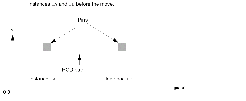
When objects do not have ROD alignments and the Maintain Connections option is on, moving instance IB causes the ROD path connecting the two pins to stretch, as shown below.
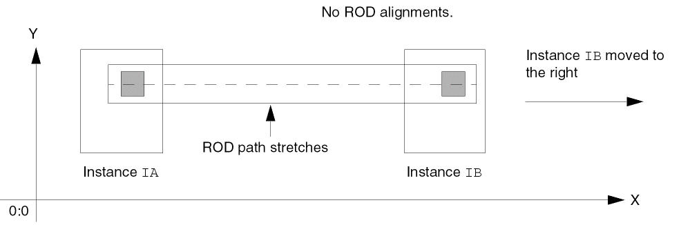
When objects do have a ROD alignment, and the Maintain Connections option is on, moving instance IB causes the whole ROD path to move, as shown below. The aligned path does not stretch, so moving instance IB breaks the electrical connection between the two pins.
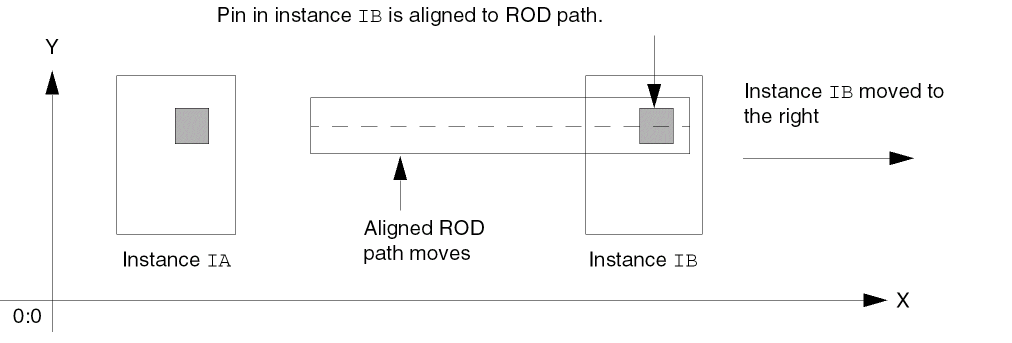
Preserving Maintained Connections
If you want the Maintain Connections option to take precedence over ROD alignments, you must either unalign the ROD objects or remove the name from one of the aligned objects. For example, to preserve the connection between the two pins shown above while moving one of the instances, you can unalign the pin in instance IB from the ROD path or remove the name from either the IB pin or the ROD path.
To unalign an object, see rodUnAlign. To remove the name from an object, see rodUnNameShape.
Return to top