1
Getting Started
The Virtuoso® Schematic Editor L and XL are design entry tools that support the work of logic and circuit design engineers, including drafters. Physical layout designers and printed circuit board designers can use the information as background material to support their work.
This user guide describes the functionality of the L and XL versions of the schematic editor:
- L version: describes the core schematic editing functionality and features that are available in the L version of the schematic editor, with additional reference to the Virtuoso® Symbol Editor.
- XL version: describes schematic functionality and features that are available in the XL version of the schematic editor and are contained within a single chapter.
This chapter discusses the following topics:
- Starting the Virtuoso Schematic Editor L/XL
- Accessing Virtuoso Schematic Editor L/XL
- Quick Reference - Menus and Bindkeys
- Quick Reference - Menu Access Keys
- Quick Reference - Toolbars
- Workspaces and Assistants in Schematics L/XL
- Additional Features of the Schematic Editor XL
- Virtuoso ADE Integration in Virtuoso Schematic Editor
- Photonics in Virtuoso Schematic Editor, ADE, and Layout XL (Virtuoso Photonics Option)
- Help and Support Facilities
- Working with Designs
- Working with Commands
- Selecting Objects
- Working With the Design Canvas Window
- The Component Browser
- Additional Features of the Schematic Editor XL
Starting the Virtuoso Schematic Editor L/XL
To start the Virtuoso Schematic Editor L you must run the virtuoso executable:
-
At a UNIX prompt in an xterm window type:
virtuoso & -
Press the
Returnkey.
The Command Interpreter Window (CIW) appears.
For details on the CIW, refer to Virtuoso Design Environment User Guide.
Accessing Virtuoso Schematic Editor L/XL
You can launch Schematics L/XL by Opening a New Cellview or Opening an Existing Cellview.
Setting Schematics L or XL as the Default Application for Viewing Schematics
You can set Schematics L or Schematics XL to be your default application by selecting File – Set Default Application and ensuring that the application required is set as the default application when viewing schematics.
For more information on setting your default application see
Quick Reference - Menus and Bindkeys
Bindkeys are used to tie commonly-used commands to single keys, key combinations, or mouse sequences. You can use the bindkeys to automate repetitive tasks and speed up your work.
For information on the default bindkeys defined for VSE L, refer to Bindkeys in Virtuoso Schematic Editor.
Menu Charts for the Virtuoso Schematic Editor
- For information on opening and closing views see
- For information on bookmarks see |
- For information on saving and restoring views, see |
Note: *Grayed out in VSE L. See Note: **Creates a Sheet menu with: Go To, Cross Reference, Go To Pin, Delete, Renumber, and Resequence menu options. |
*- For more information on the Annotation Browser, see the - For more information on window components see the Virtuoso Design Environment User Guide. |
- For more information on the RF-Module menu options, see the |
- For more information on window components, such as Workspaces and Toolbars, see the Virtuoso Design Environment User Guide. |
Menu Charts for the Virtuoso Symbol Editor
|
|
||
|
- For information on opening and closing views see
- For information on bookmarks see |
- For information on saving and restoring views, see |
- For more information on window components, such as Workspaces and Toolbars, see the Virtuoso Design Environment User Guide. |
||||
Bindkey Storage
Cadence-provided bindkeys, which are loaded by default, are located in the following directory:
<cds_install>/share/cdssetup/dfII/bindkeys/
Here, the following definition files are available, and loaded, when the respective application is launched:
You can control the loading of default bindkeys through the use of the following environment variable:
schematic autoLoadBindKeys boolean t/nil
Customizing Bindkeys
You can set new bindkeys, or override default bindkeys, by creating a corresponding SKILL (.il) file, and placing it in the search path that is defined by the default setup.loc file and/or the CSF mechanism.
The following locations are recommended for customization at the design level, user level, project level, or company level, respectively:
-
./.cadence/dfII/bindkeys/ -
~/.cadence/dfII/bindkeys/ -
$CDS_PROJECT/.cadence/dfII/bindkeys/ -
$CDS_SITE/.cadence/dfII/bindkeys/
$CDS_SITE will be loaded first, then $CDS_PROJECT, and so on.- Specifying CSF Search for Additional Files and Cadence Setup Search File: setup.loc in the Cadence Application Infrastructure User Guide
- Bindkeys and Access Keys in the Virtuoso Design Environment User Guide
- hiSetBindKey in the Cadence User Interface SKILL Reference
Quick Reference - Menu Access Keys
Menu access keys provide keyboard access to functionality and application menus without the need to use mouse selections.
For example, selecting the Alt + F access keys together will display the contents of the File banner menu.
Menu access keys should not be confused with bindkeys, for example those detailed in the Quick Reference - Menus and Bindkeys, as bindkeys do not require a menu to be displayed before a bindkey “shortcut” can be used.
For example, if you want to open the Editor Options form directly you can use the “O” (Shift + O) bindkey. It is not necessary to use the Edit menu access keys (Alt + E) to first of all display the contents of the Edit menu.
Once you have used access keys to display the contents of the Launch menu you can then use a further access key to select an application menu to be added to the banner menu. After an application menu has been added to the banner menu you can then use their associated access keys to display their menu content.
For example, to display the content of the AMS menu on the banner menu you would:
-
Select the access keys
Alt + L(this displays the content of the Launch menu). -
Select the access key
R(this adds the Parasitics menu to the banner menu) -
Select the access keys
Alt + R(this displays the content of the Parasitics menu on the banner menu).
Access Keys - Schematic Editor L
The following table details the menu access keys for the Virtuoso Schematic Editor L:
Access Keys - Virtuoso Symbol Editor
The following table details the menu access keys for the symbol editor:
Quick Reference - Toolbars
The following toolbars are available for selection in both the Virtuoso Schematic (and Symbol) Editor L and XL (unless specifically stated).
-
File toolbar
Options: New / Open / Check and Save / Save
-
Edit toolbar
Options: Move / Copy / Stretch / Delete / Edit Properties / Direct Text Edit / Repeat Last Command / Undo / Redo / *Rotate / Increase Text Size / Decrease Text Size/ Align/ Distribute * The Rotate option has a pull-down where you can choose to either Rotate Right, Rotate Left, Flip Horizontal, or Flip Vertical. See also Rotating.
 -
View toolbar
Options: Zoom In / Zoom Out / Zoom to Fit / Zoom to Selected
-
Create (Schematics) toolbar
Options: Create Instance / Create Narrow Wire / Create Wide Wire / Create Wire Name / Create Pin / Command Options
-
Create (Symbol) toolbar
Options: Create Rectangle / Create Label / Create Pin / Create Circle / Create Polygon / Create Ellipse / Create Line / Create Arc / Create Note
-
Search toolbar
Options: Search Categories / Search / Search History / Advanced Search
-
Select toolbar
Options: Default Selection Filter / Instance Select Filter / Wire Select Filter / Pin Select Filter/ Text Select Filter / Open Selection Filter
-
Design Intent toolbar
Options: Annotation Show/Hide / Glyph Show/Hide / Halo Show/Hide / Delete all DI in Cellview / Report
For more details see, Virtuoso Design Intent User Guide. -
RF toolbar (Virtuoso RF Solution Option)
Options: Inflate / Create Net Topology / Create Stackup / analogLib cap symbol / analogLib capq symbol / analogLib ind symbol / analogLib indq symbol / analogLib res symbol / analogLib presistor symbol and includes shortcuts to access the transmission line components from the library. For more details, see RF Transmission Lines.
-
Bookmarks toolbar
Options: (list of bookmarked views)
For more information on the Bookmarks toolbar see Using Bookmarks and Views in the Virtuoso Design Environment User Guide. -
Go toolbar
Options: Back / Forward / Up / Top
For more information on the Go toolbar and design navigation see Navigating Cellviews and Hierarchies in the Virtuoso Design Environment User Guide. -
Workspaces toolbar
Options: Workspace Configuration / Save Workspace / Toggle Assistants Visibility
For more information on the Workspaces toolbar see Working with Workspaces in the Virtuoso Design Environment User Guide.
See also
Workspaces and Assistants in Schematics L/XL
You can use the Cadence provided workspaces as well as your own, new,
Workspaces and assistants are available in both in VSE L and VSE XL (there are also additional Constraint-related workspaces in VSE XL).
Schematic Editor Workspaces
Schematics L/XL workspaces can be accessed from:
Schematics L provides access to the following workspaces:
- The Basic workspace which is the default workspace contains The Navigator Assistant and The Property Editor Assistant.
-
The Classic workspace where selection will remove all assistants from the current session window.
-
The Explore workspace which contains The Navigator Assistant, The Search Assistant and The Property Editor Assistant.
Additionally, as well as displaying the standard toolbars (File, Edit, View, Select and Create), the Explore workspace will also ensure that the Search, Go, and Bookmark toolbars are displayed.For more information on all of these toolbars see Quick Reference - Toolbars.
Additionally, to all of the above workspaces, the Virtuoso Schematic Editor XL also has the following workspaces:
-
The Constraint-Helper workspace
Contains the Constraint Manager Assistant and the Circuit Prospector Assistant.
For more information on constraints and their related workspaces, see the Virtuoso Unified Custom Constraints User Guide. -
The Constraints workspace
Contains The Navigator Assistant, The Search Assistant and the Constraint Manager Assistant. -
The Design Intent workspace
Contains the Design Intent toolbar, The Navigator Assistant, The Navigator Assistant and The Property Editor Assistant.
For more information on design intent and the related workspace, see the Virtuoso Design Intent User Guide. -
The Power workspace
Contains the The Navigator Assistant and The Property Editor Assistant. -
The RF workspace (Virtuoso RF Solution Option)
Contains the RF-Module Menu, RF toolbar, The Navigator Assistant and The Property Editor Assistant. For more details, see the Virtuoso RF Solution Guide.
Schematic Editor Assistants
Schematic Editor assistants can be accessed by selecting Window – Assistants.
The Schematic L and XL have the following assistants:
- The Navigator Assistant
- The Search Assistant
- The Property Editor Assistant
- The World View Assistant
-
The Annotation BrowserFor information on the Annotation Browser, see the Annotation Browser in the Virtuoso Layout Suite XL User Guide.
In addition to these assistants, Schematics XL also has the following assistants:
Assistant Pane Keyboard Shortcuts
The following table lists all the (non-configurable) keyboard shortcut controls you can use when working with assistant panes in the Virtuoso Schematic Editor.
| Key Combination | Action | Key Combination | Action |
Additional Features of the Schematic Editor XL
Schematics XL provides the following additional features:
-
Schematic HTML Publisher
Virtuoso Schematic Editor XL provides the ability to export a schematic design hierarchy to HTML.
For more information, see Exporting a Schematic Hierarchy to HTML. -
Constraint Management
Constraint management functionality allows for the addition, modification, and deletion of constraints from/to the Cadence constraint storage system.
For more information see Constraint Management in Schematics XL and the Virtuoso Unified Custom Constraints User Guide. -
Design Intent
Design intent is a collaboration tool that uses annotations as a means for schematic designers to capture and communicate design goals in Schematics XL and provide layout designers with the freedom to decide how to implement those goals in Layout XL.
For more information see the Virtuoso Design Intent User Guide.
Constraint Management in Schematics XL
Schematics XL also provides advanced constraint management functionality through two constraint assistant panes:
The Constraint Manager Assistant
The Constraint Manager assistant pane allows for the addition, modification, and deletion of constraints from/to the constraint storage system. These constraints consist of the likes of matching, symmetry, orientation, relative orientation, IR drop, clustering, alignment, area, distance, boundaries, power structure (guard rings), custom module generators (modgens), cell plans, and analog groups.
The Constraint Manager also keeps track of all added constraints by grouping constraints by instance or constraint type. Each constraint can be modified, for example symmetry can be changed from mirror to simple using the Constraints Editor.
As well as the above, you can also add notes, set priority and change the status of a constraint.
You can access the Constraint Manager by
- Selecting Window – Assistants – Constraint Manager.
- Selecting Constraint Manager from the Toolbars context-sensitive menu.
- Selecting the Constraints or Constraint-Helper workspaces from the Workspace Configuration pull-down menu on the toolbar (or selecting Window – Workspaces Constraints/Constraint-Helper).
For more information see
The Circuit Prospector Assistant
The Circuit Prospector assistant pane provides three main elements of functionality to assist the creation of constraints in The Constraint Manager Assistant:
-
The ability to find structures in a schematic view.
The current set of structures automatically recognized include devices in the same well, symmetric devices, devices of the same cell name, MOS current mirrors, MOS differential pairs, MOS common gates, and so on. -
The ability to modify the structure finders.
This means that you can modify an existing finder in order to customize it. For example, the finder for MOS common gate can be modified to create a finder for BJT common base. -
The ability to create a customized finder based on selected topologies.
Here, you can select devices and nets in the schematic view which represent a custom structure. You would capture this structure, name the finder for the structure, and then use this finder to locate all structures of this type.
You can access the Circuit Prospector by:
- Selecting Window – Assistants – Circuit Prospector.
- Selecting Circuit Prospector from the Toolbars context-sensitive menu.
- Selecting the Constraint-Helper workspace from Windows – Workspaces or the Workspace Configuration toolbar pull-down.
For more information see
Virtuoso ADE Integration in Virtuoso Schematic Editor
You can launch Virtuoso ADE Explorer or Virtuoso ADE Assembler from Virtuoso Schematic Editor (VSE) or vice versa by using the VSE menu. Virtuoso ADE toolbars are then displayed along with the VSE toolbars. The VSE window title bar is updated to state whether you are working in ADE Explorer or ADE Assembler mode.
For more information, see
Photonics in Virtuoso Schematic Editor, ADE, and Layout XL (Virtuoso Photonics Option)
The EPDA Framework has been built by using the three main Virtuoso applications: Virtuoso Schematic Editor, Virtuoso Analog Design Environment, and Virtuoso Layout Suite. Spectre is also used to enable true Electrical - Photonics co-design.
Optical pins, which are an essential part of a photonics solution, are created by defining the signal types as optical. It further contributes in creating the optical ports and waveguides that can be identified by assigning a distinctive color and line style.
VSE and VLS support the optical signal types optical, singleModeOptical, and multiModeOptical during editing, connectivity extraction, and checking as part of this feature. For example,
- Preserving optical signal types during extraction.
- Propagating optical signal types from instance terminals.
- Resolving mixed optical signal types during propagation.
- Applying the optical wire style after connectivity extraction.
- Running optical checks after connectivity extraction.
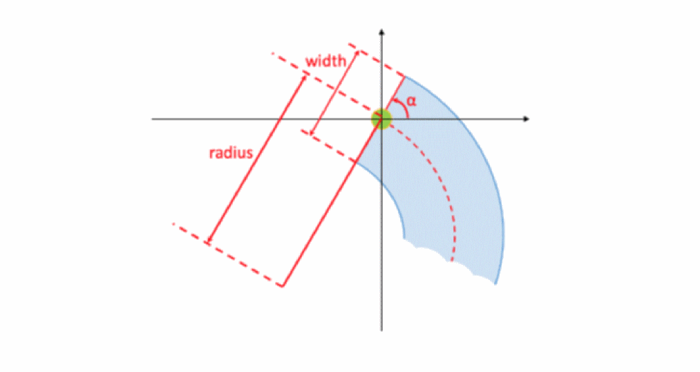
In photonics, waveguides are also one of the basic building blocks. They are used to guide light as optical modes and can be curved. Each photonic port is associated with an access to an optical (photonic) waveguide.
There are three properties associated with every photonic port:
- Width width of the waveguide associated to the port
- Radius curvature of the waveguide associated to the port
- Angle access direction to the photonic port
In photonics processes, waveguides are necessary in order to guide light along a path. In Virtuoso, waveguides can be generated as connected Pcells or fixed layouts.
Figure 1-1 Photonics Waveguide
Waveguide Editor allows editing of the waveguides. It can be accessed from VSE as well as VLS.
Refer to the following links to know more about the photonics solution in Virtuoso:
- Editing the Optical Signal Types
- Propagating Optical Signal Types (Virtuoso Photonics Option)
- Optical Checks (Virtuoso Photonics Option)
- Editing the Optical Signal Types in Property Editor (Virtuoso Photonics Option)
- Photonics Environment Variables (Virtuoso Photonics Option)
- Using opticalLib to Create PDK (Virtuoso Photonics Option)
- Rotating Objects
- Create Pin Options
- Edit Properties Options
- Generating Optical Pins for the Virtuoso Photonics Solution
- Editing Composite Waveguides
- Composite Waveguide Editor
- Abutment in Virtuoso Photonics Solution
- Photonic Interprocess Communication Functions
Help and Support Facilities
The following help and support facilities are available as Help menu options:

Contextual Cursors
Each enter function in the schematic editor has a specific cursor to distinguish which action is currently being performed (for example, direct text edit, selection, delete, add instance, and so on).
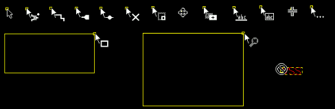
Figure 1-2 Examples of Contextual Cursors Used in the Schematic Editor
See also hiSetCursor in the Cadence User Interface SKILL Reference.
Working with Designs
The following section describes the basics about the schematic editor and the symbol editor.
- Opening a New Cellview
- Opening an Existing Cellview
- Using the Schematic Window
- Using the Symbol Editor
- Making Designs Editable
- Making Designs Read Only
- Saving Your Edits
- Closing Editor Windows
- Quitting the Virtuoso Schematic Editor
- Viewing a Design in Schematic Assistant of Virtuoso Studio Layout Suite
Opening a New Cellview
To open a new cellview from the schematic editor:
-
Choose File – New.
The New File form appears.
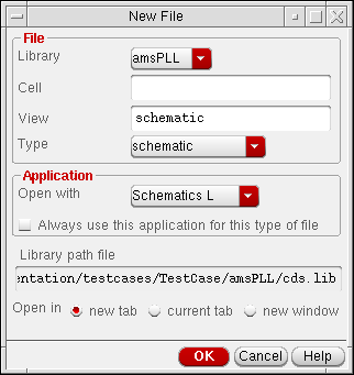
- In the Library pull-down choose the library in which to store the new cellview.
- In the Cell field enter a new cell name or leave as-is with the current cell name entered.
- In the View field enter a name for the new cellview.
- In the Type pull-down choose the view type, for example schematic or config, that is to be associated with the new cellview.
- In the Open with field choose the application that the new cellview should automatically be opened with.
-
Optionally, check the Always use this application for this type of file checkbox to associate the selection made in the Open with field with the current View type selected.
This will save you in future having to select what application should be opened with a selected cellview Type. -
Choose whether you want to open the new cellview in a new tab, the current tab, or in a completely new window.
- Click OK.
Opening an Existing Cellview
To open an existing cellview in the schematic editor:
-
Choose File – Open from an editor window or the CIW.
The Open File form appears.
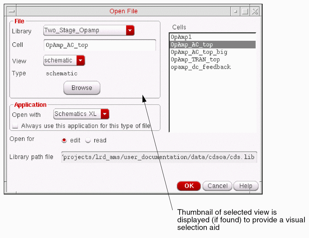
- In the Library pull-down choose the library that contains the existing cellview.
- In the Cell field specify a cell name to open by doing one of the following:
-
Choose the cellview to be opened from the pull-down.
The Type field will update to display the type of view of the selected cell view. - In the Open with field choose the application that the cellview should be opened with.
-
Optionally, check the Always use this application for this type of file checkbox to associate the selection made in the Open with field with the current View type selected.
This will save you in future having to select what application should be opened with a selected cellview Type. - Choose to open the cellview in edit or read mode.
- Choose to open the cellview in a new tab in the current session window, the current tab in the current session window, or a new window in a new session.
- Click OK.
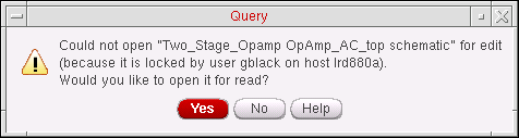
Cellview Already in Use
If you attempt to open a cellview that is already being used (that is, the cellview file is locked by another user), a warning message will be displayed informing you of the current user of the cellview and the current host machine name.
From here you can choose to either open the cellview as read-only or not to open the cellview.
Using the Schematic Window
A schematic design is a graphical representation of an electronic circuit design. The
You can then to choose add a range of objects to the schematic canvas including the following:
You should use the symbol editor to draw symbols that you place in the schematic window. For more information see Using the Symbol Editor.
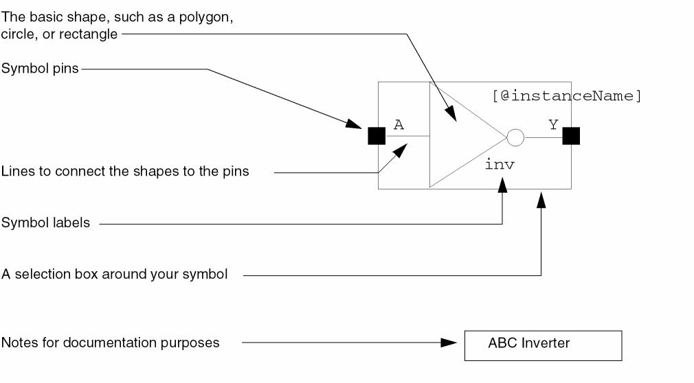
Using the Symbol Editor
When a schematic design requires a symbol that does not have a corresponding symbol in a Cadence library, you can create your own symbol using the symbol editor. After you create the master symbol, you can add a copy of it (known as an instance) to your design using the schematic editor.
If you later change a master symbol, the schematic editor automatically applies the changes to all the existing instances of that symbol, as well as to any new instances you might add.
The only differences visually between the schematic editor and the symbol editor are the commands.
You use the symbol editor to add the following graphics.
Making Designs Editable
If you opened your schematic or symbol in read-only mode, you can change the mode to make it editable.
This command toggles with File – Make Read Only.
Making Designs Read Only
To make a design open in read-only mode,
-
Choose File – Make Read Only.
If you have made any changes to the current cellview but have not saved them, the Change Edit Mode dialog box appears and prompts you to either save the changes or discard them
After you click Yes or No, the mode becomes read only.
This command toggles with File – Make Editable.
Saving Your Edits
To save a design to a different name,
-
Choose File – Save a Copy.
The Save a Copy form appears.
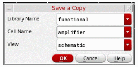
- Change the form fields (in the Library Name, Cell Name, and View fields) to a filename of your choice.
- Click OK.
The Save options can also be used to store any changes made, for example the creation or removal of constraints, in the Constraint Manager assistant pane. You may therefore, when using constraints management, see a Save (Constraints) option. The Constraints Manager is only available in Schematics XL. For more information see Virtuoso Unified Custom Constraints User Guide.
Thumbnail images, where they have been set up in the current view for pre-viewing cellviews, are updated automatically when you choose to Save or Save a Copy of that cellview. This is actioned by an automatic call to the hiGenerateThumbnails command.
To disable auto-generation of thumbnails, set the following environment variable in .cdsenv:
ui.thumbnails generate boolean t
For more information on the use of thumbnails see
Closing Editor Windows
-
Choose File – Close.
If you edited the current cellview since the last time you saved your data, the Save Changes dialog box appears and prompts you to save the changes, discard them, or cancel the Close operation.
Yes saves your edits and closes the window.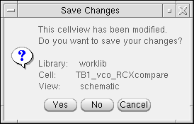
No discards your edits and closes the window.
Cancel cancels the Close command but does not discard the changes. It returns you to the cellview you were editing.
Quitting the Virtuoso Schematic Editor
To quit the Virtuoso schematic editor
-
From the schematic editor session window choose File – Close/Close All.
If you have not saved your edits, the Save Changes form appears. - Specify one of the save options by clicking on the corresponding button.
-
Click OK.
If you click Cancel on the Save Changes form, you cancel both the save and the quit operations, and the software continues to run.
For information about saving your environment, saving your session, or viewing your log file, refer to Virtuoso Design Environment User Guide.
Viewing a Design in Schematic Assistant of Virtuoso Studio Layout Suite
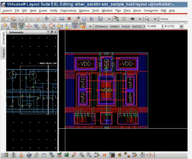
While working with the layout, a layout designer often needs to refer to the design components in the schematic. Either you can keep the design open in the Virtuoso Schematic Editor window along with the Layout Editor window and switch between two, or you can use the Schematic assistant in Virtuoso Studio Layout Suite to view the schematic in read-only mode.
The Schematic assistant is an assistant in the layout editor that displays the current design as displayed in the schematic editor. In this assistant, you can move around and zoom in and out on the design as normal, and you can select parts of the design as if you were using the schematic editor. This assistant also lets to use the cross-probing and cross-selection features of the schematic editor.
To start the Schematic Assistant, using Virtuoso Studio Layout Suite XL or higher, select Window – Assistants – Schematic.
To make the assistant part of the default view in Virtuoso Studio Layout Suite:
- Select Options – Connectivity to open the Connectivity form.
-
In the Connectivity Reference area, set Open with: to No Schematic.
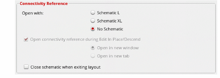
- Click OK.
-
On the Workspaces toolbar, select Save Workplace.
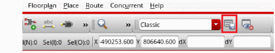
- Enter a name for your new workspace.
-
Click OK to save the workspace.
The new workspace now contains the Schematic Assistant by default.
The Schematic assistant works only in preselect mode, that is, you must select an object in the assistant or in the schematic editor before it can be interacted with.
Related Topics
Schematic Assistant Right-Click Menu
When you right-click inside the Schematic Assistant, the following pop-up menu appears:
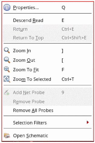
The various options available are:
- Properties: Opens the Edit Object Properties form.
- Descend Read / Return / Return To Top: Navigates around the schematic hierarchy.
- Zoom In / Zoom Out / Zoom To Fit / Zoom To Selected: Zooms on the schematic canvas.
- Add Net Probe: Adds a net probe to the selected object.
- Remove Probe: Removes selected net probe.
- Remove All Probes: Removes all net probes.
- Selection Filters: Lets you define the selection filters.
-
Open Schematic: Opens the schematic in the Virtuoso Studio Schematic Editor.
Related Topics
Edit Object Properties – Basic
Working with Commands
The following sections provide information about working with commands.
Using Command Prompts
After you start a command the prompts at the bottom of the schematic editor window will direct you as to what to do next.
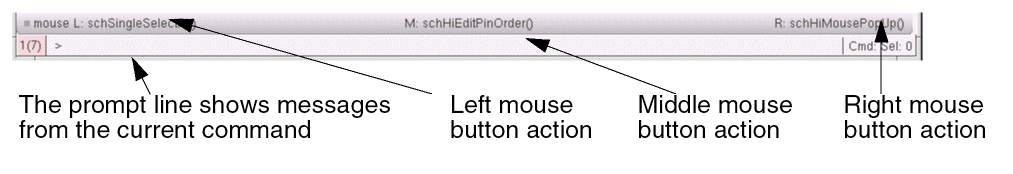
The mouse settings line shows the current settings for the mouse buttons. The settings change as you move the mouse in and out of design windows or start and stop commands.
For example:mouse L:schSingleSelectPt = enter a pointM:schHiEditPinOrder = repeats last command (open Pin Order form)R:schHiMousePopUp = popup menu
Canceling a Command
To cancel a command, do one of the following:
Undoing a Command
To undo a command, do one of the following:
Redoing a Command
To redo a command (that is, undo an undo), do one of the following:
Selecting Objects
This section describes the following topics:
- Dynamic Highlighting
- Extending the Selection Area of a Net
- Selecting One Object
- Selecting Multiple Objects
- Selecting Parts of Objects
- Selecting Wires
- Selecting a Wire Name and Its Associated Wire Segments
- Selecting a Pin and Its Associated Wire Segments
- Selecting an Instance and Its Associated Wire Segments
- Deselecting Objects
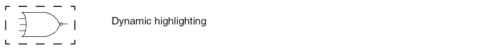
Dynamic Highlighting
When you move the pointer over an object, the object is automatically highlighted. This behavior is called dynamic highlighting. It helps you in identifying the object that will be:
- selected on left-click
- affected by a direct manipulation command
-
affected by a command when infix is selected on the User Preferences form
The object is highlighted with a yellow dashed line.
Dynamic Net Highlighting
The dynamic net highlighting feature can be enabled by selecting the Net Highlighting menu option on the View menu. Consequently, when you move the mouse pointer over a selectable net, or block, any other associated objects are also highlighted and the names of these objects are displayed on the status bar.
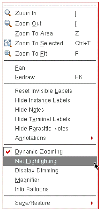
Figure 1-3 Net Highlighting Option in the View Menu
Alternatively, you can enable this feature by selecting the "on" radio button corresponding to Dynamic Net Highlighting in the Display Options.
You can also use schDynamicNetHilightOn to specify whether the schematic editor dynamically highlights all objects of the same net when the mouse pointer is placed over objects.
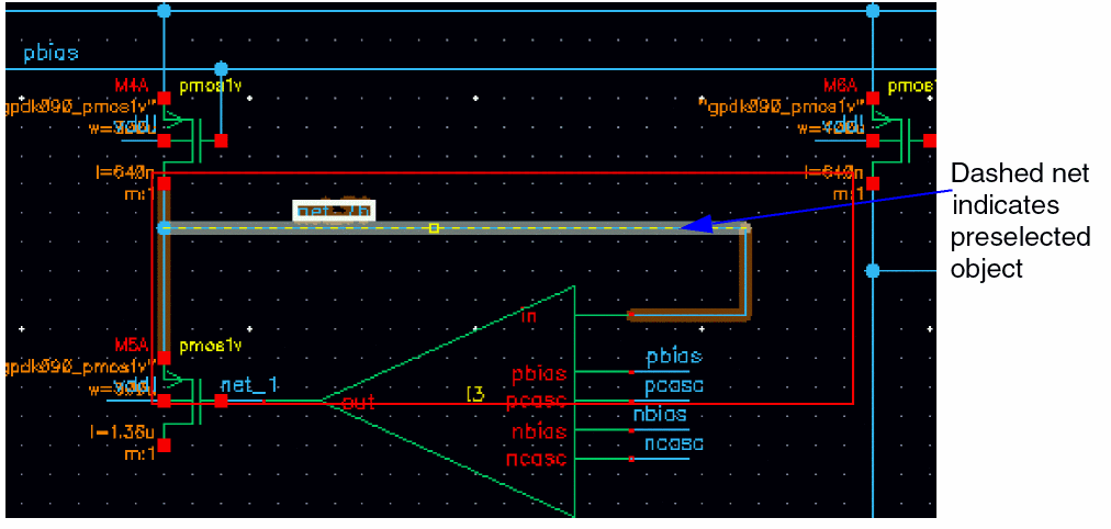
Figure 1-4 Net Highlighting Switched On
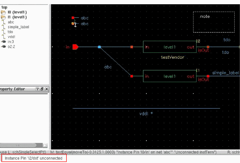
Highlighted Object Names on Status Bar
The name of the highlighted objects are displayed on the status bar along with the connected net name. You can use objectInfoInStatusBar to control the display of information about the selected objects on the status bar.
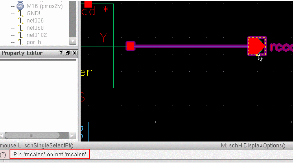
When the pin does not have any connectivity, unconnected is displayed on the status bar along with the pin name, as shown below.
If the same net is used in different areas of a design and has several associated objects, arcs are drawn between islands when this common net is highlighted. When you move the mouse pointer over an associated object, all the other objects on the same net are also highlighted. In addition, a reference dynamic arc is drawn from the object on which the mouse pointer is currently placed to all the other same net islands.
Highlight Colors
When the design is up to date and has not been modified since last save, by default, the following colors are used for highlighting the objects:
-
magentais used for highlighting the objects under the pointer as well as the objects attached to the objects under the pointer. -
cadetBlueis used for highlighting the member nets and the objects on the member nets.
When the design is not up to date, the default colors for highlighting the objects are the same as those listed above. However, orange color is used to highlight the objects attached to the object under the pointer.
You can use the following environment variables to set the default color for highlighting the objects:
-
schDynamicNetHilightColor
Specifies the color for the objects on the same net as the preselected object when the connectivity is up to date. The default color for highlighting ismagenta. -
schDynamicNetHilightColorAlt
Specifies the color for the objects on the same net as the preselected object when the connectivity is not up to date. The default color for highlighting isorange. -
schDynamicNetHilightColorPre
Specifies the color for the preselected highlighted object that is under the cursor. The default color for highlighting ismagenta. -
schDynamicNetHilightColorMemNet
Specifies the color for the objects on the member net of the preselected object. The default color for highlighting iscadetBlue.
Extending the Selection Area of a Net
When you want to copy, move, stretch, or delete an entire section of a net, you need to extend the selection area of all physically connected wire segments.
An entire section of a net ends at
- Any three-way or four-way wire connection point
- An instance pin
- A schematic pin
- A change in wire width (bus)
You can use extended selection to select the following:
- Several wire segments
- A wire name and its associated wire segments
- A pin and its associated wire segments
- An instance and its associated wire segments
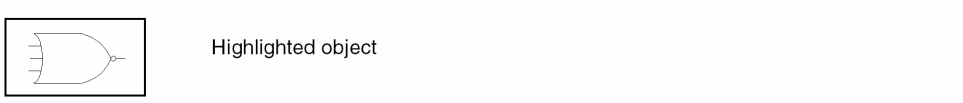
Selecting One Object
To select one object to copy, move, stretch, or delete,
-
Move your cursor over the object.
Dynamic highlighting shows you which object will be selected when you click the mouse button.
-
Click the mouse button.
The selected object is highlighted.
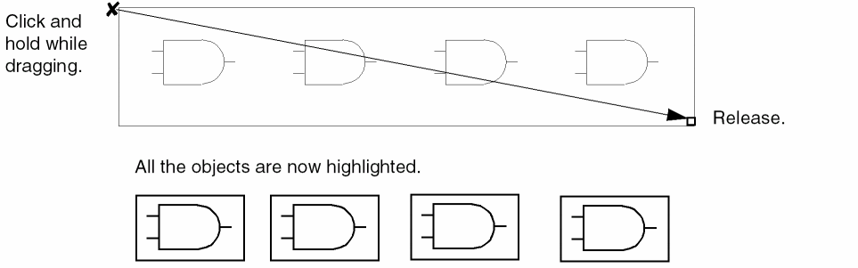
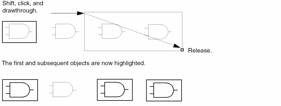
Selecting Multiple Objects
There are three ways to select multiple objects:
-
Shift–click (hold down theShiftkey and click) on each object that you want to add to the set -
Drag a box completely around all the objects that you want to select
- Select one object, and drag a box completely around the other objects that you want to add to the selected set
-
Hold down the left mouse button while you drag a box completely around all the objects you want to select.
-
Click the first object and then hold down the
Shiftkey and the left mouse button and drag a box completely around the objects you want to add to a selected set.
Selecting Parts of Objects
Selecting a part of an object is important when you want to
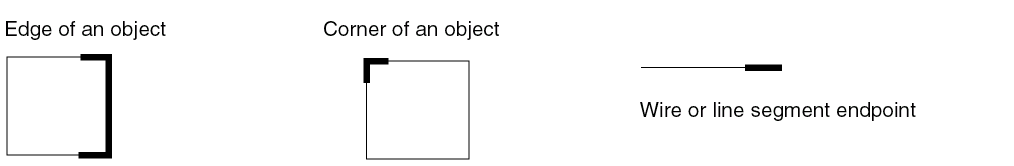
You can select parts of schematic wires, note shapes, symbol lines, and symbol devices.
Selecting Wires
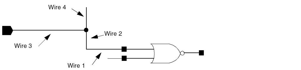
To select several physically connected segments of one wire,
- Click Wire 1 to select the first wire segment.
-
Shift-double-click Wire 1 to select both Wire 1 and Wire 2.
The extended selection grows to include all segments up to a branch. -
Shift-double-click again on Wire 1 to select all the connected wires (Wires 2, 3, and 4).
All segments of the network that are physically connected are selected and highlighted.
Selecting a Wire Name and Its Associated Wire Segments
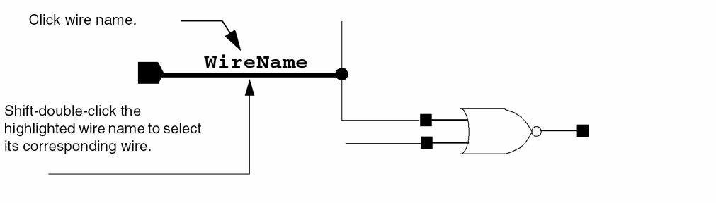
To select a wire name and its associated wire segments,
- Click the wire name to select it.
- Shift-double-click the already selected wire name to select its associated wire segment.
Selecting a Pin and Its Associated Wire Segments
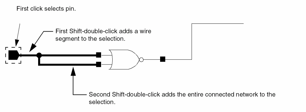
To select a pin and its associated wire segments,
- Click a pin to select it.
-
Shift-double-click the selected pin.
This selects the wire segment connected to the pin. -
Shift-double-click again on the selected pin.
This extends the selection area to all physically connected wire segments.
Selecting an Instance and Its Associated Wire Segments
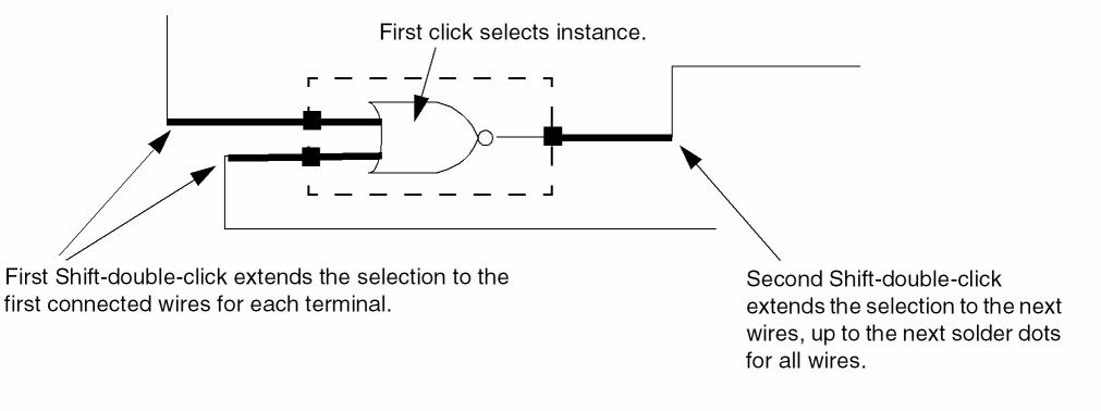
To select an instance and its associated wire segments,
- Click an instance to select it.
-
Shift-double-click the selected instance.
Extends the selection to the first connected wires for each terminal. -
Shift-double-click again on the instance.
Extends the selection to the next wires, up to the next solder dots for all wires.
Deselecting Objects
You can use the mouse to deselect objects.
The following table summarizes how you can use your mouse to deselect objects in a design window:
| Action | Result |
|---|---|
|
Deselects all objects if not within a command. If in a repeat command, use |
|
To deselect all objects, click in an open area of your design.
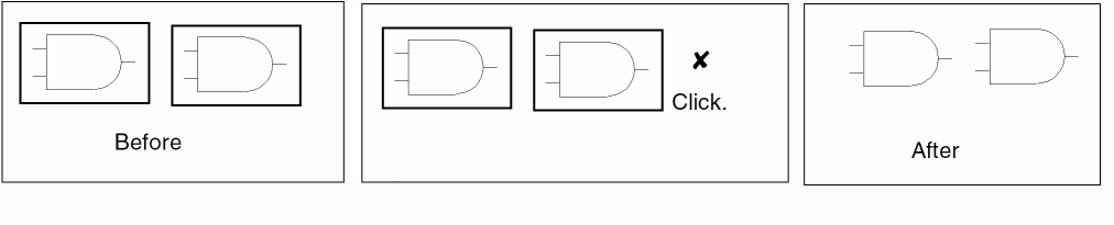
To deselect one object and select another, click the second object.
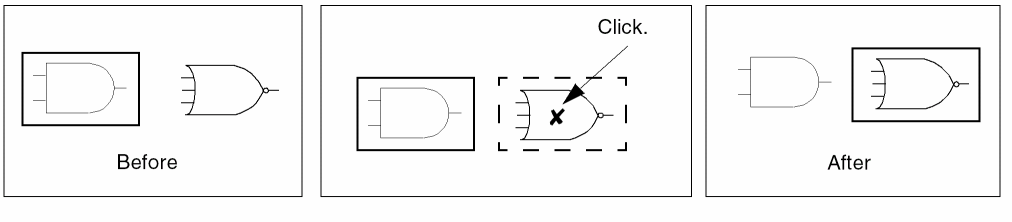
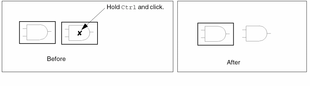
To deselect only one object from a selected set, hold down the Ctrl key and click the object you want to deselect.
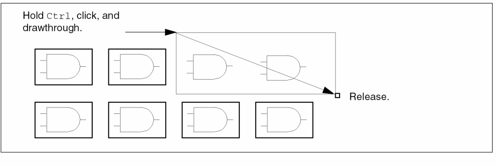
To deselect more than one object from the selected set, hold down both the Ctrl key and the left mouse button while dragging a box around the objects you want to deselect.
Using Strokes
A stroke is a unique shape that you can draw in a cellview by pressing and holding down the right mouse button.
Cadence ships a set of pre-defined strokes for Virtuoso that you can load from the Cadence installation hierarchy. This loading must be done before attempting to use strokes.
For more information, see Loading and Unloading Strokes in the Virtuoso Layout Suite L User Guide.
Working With the Design Canvas Window
The following commands describe how to quickly navigate around the main canvas window and view and manipulate windows.
- Zooming
- Panning
- Using the Magnifier
- Redrawing a Window
- Viewing the Same Cell in Two Windows
- Saving View Area Settings in Memory
- Restoring View Area Settings
Zooming
Zooming is helpful as you add and edit objects. For example, you can view objects in two windows at the same time and use a different zoom factor in each.
Zooming In Manually
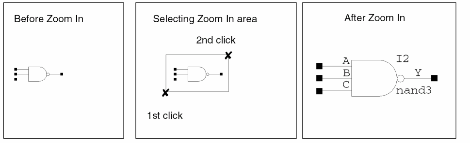
To zoom in (decrease the display area) manually,
- Choose View – Zoom In.
- Click your cursor to mark one corner of the zoom area.
-
Click your cursor to mark the other corner of the zoom area.
Zooming In Automatically
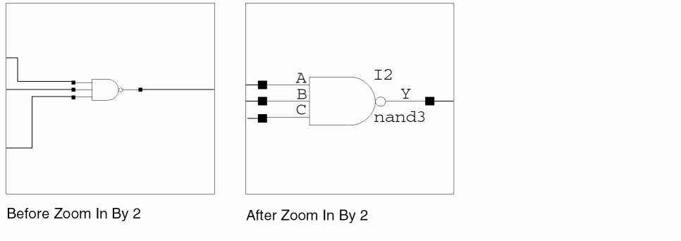
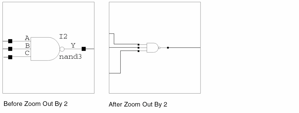
To zoom in automatically by 2 (decrease the display area by a factor of 2),
Zooming to Selected Objects
-
Select the object(s) that you want to look closer at.
-
Choose View – Zoom To Sel Set.
When this option is selected, the window zooms to a maximum magnification so that all the selected objects are visible in the window.
You can also access this functionality from the Multiple Selection and Instance Pop-Up menus, and via the CIW using the schHiZoomToSelSet command.
Zooming Out Automatically
To zoom out by 2 (increase the display area by a factor of 2),
Zoom to Fit Automatically
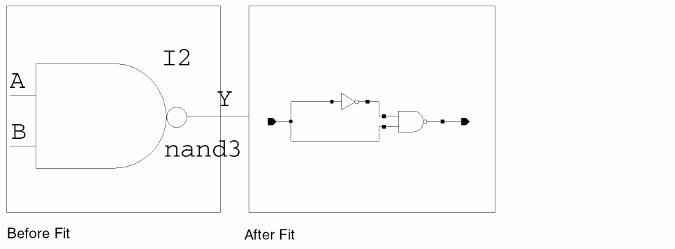
To zoom to fit (resize the display area to show the entire cellview in the window),
Dynamic Zoom and Pan
You can use dynamic zoom and pan to go directly to any object/constraint selections made in, for example, the Navigator and Constraint Manager assistants.
To activate dynamic zoom and pan, to objects on the design canvas, ensure that the View – Dynamic Zooming option is active. The default for this option is on.
The dynamic zoom setting can be set to one of the following modes: Pan To Selected, Zoom To Selected, or Zoom To Fit.
See also autoZoomPan, autoZoomMode, and autoZoomScale.
To set the preferred dynamic zoom setting:
-
Select Options – Display.
The Display Options form is displayed.
Figure 1-5 Display Options Form with Zoom/Pan Controls for Dynamic Zooming Highlighted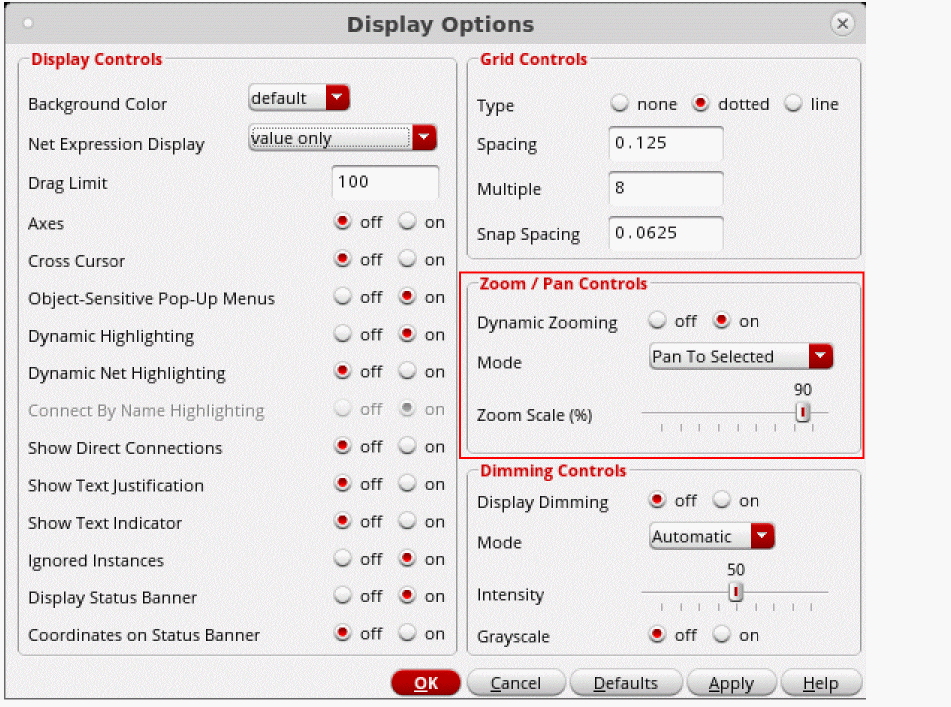
- Ensure that the Dynamic Zooming option is set to on.
-
Choose the dynamic zoom Mode that you want to use:
-
Pan To Selected
This is equivalent to View – Pan. Where, whenever an object, or a set of objects, is selected/cross-selected in an assistant, the view will pan to have the first object visible in the center of the canvas without changing the zoom factor. If the selected object is already visible in the canvas, the view will not pan to center. -
Zoom To Selected
If this mode is selected, dynamic zoom will perform an auto-zoom (the equivalent of View – Zoom To Selected) that ensures that all selected objects are visible in the design canvas window display. -
Zoom To Fit
If this mode is selected, a View – Zoom To Fit command will automatically be run after each object selection/cross-selection is made in an assistant.
-
Pan To Selected
- Move the slider to specify the Zoom Scale(%).
- Click OK to apply the Zoom / Pan Controls updates.
Display Dimming
Select View – Display Dimming to toggle on and off object dimming in the schematic canvas when an object is selected in, for example, the Constraint Manager or the Navigator assistant.
Figure 1-6 Display Dimming Off (Default)
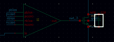
Display dimming allows you then to dim the display of all objects in the canvas except for those objects that are either currently selected, highlighted, or being probed.
You can control dimming display using the Dimming Controls in the
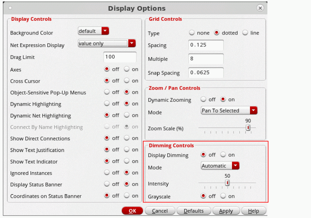
Figure 1-8 Dimming Controls in the Display Options Form
- Display Dimming lets you set dimming on or off. When on is selected, the View – Display Dimming option is activated which controls the current dimming setting. See also dimming.
- Mode lets you choose whether dimming be Automatic (the default); where dimming will only be enabled when at least one object is currently selected, highlighted, or being probed. Or, choose to set dimming to Always which will enable dimming permanently (until the option setting is changed). See also dimmingMode.
- Intensity lets you set the intensity (brightness) display of the dimmed objects, where 0 equals the dimmed object display being the same as the selected object, up to 100 which will cause the dimmed objects to be “invisible” on the canvas. The default setting is 50. See also dimmingIntensity.
Panning
Panning lets you reposition your design within the editor window, which is helpful when you want to add, view or edit objects.
- Your cursor and the View – Pan command
- The arrow keys on your keyboard
- The editor window scroll bars
- Assigned bindkeys
Panning Using Your Cursor and the View – Pan Command
- Choose View – Pan.
-
Click the point that you want to appear in the center of the editor window (the reference point).
The image moves and places the reference point in the center of the editor window.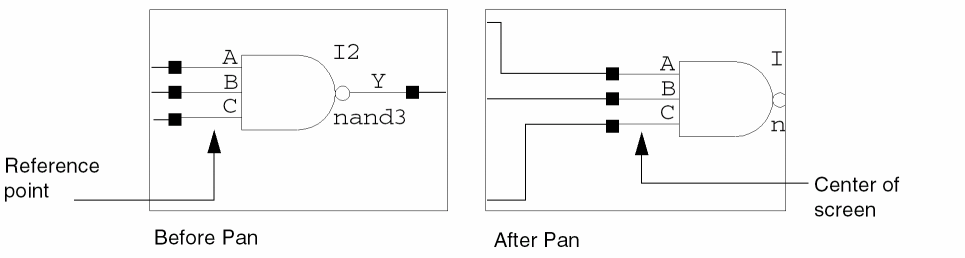
Panning Using Zoom to Selected
To automatically pan to an object in the design canvas:
-
Ensure that the View – Zoom To Selected menu option is checked.
This option is “on” by default. -
Select an object in either the Navigator and Search assistants.
If the object is located outside of the visible pane, VSE will now automatically pan to that object in the design canvas.
Panning Using the Arrow Keys
To pan using the arrow keys on your keyboard,
Panning Using the Editor Window Scroll Bars
To pan using the vertical and horizontal scroll bars on the editor window,
-
From the CIW, choose Options – User Preferences.
The User Preferences form appears. - Set Scroll Bars to on.
-
Click OK.
Using the Magnifier
The magnifier allows you to zoom into a specific area of the design canvas, rather than the design canvas.
When the magnifier is first launched, it will display in accordance with the current, related, variable settings in the .cdsenv file for the current root application type (for information on how these settings can be amended for future invocations of the magnifier, see
maskLayout”, schematicSymbol”, or “schematic” (as returned by deGetRootType). The magnifier.cdsenv setting values are also stored based on the root application type, therefore if a sub-application of, for example, schematic has its own .cdsenv variables, then it would still need to have them set at the root application level for them to take effect.To activate the magnifier on the design canvas:
-
Place your cursor over the area in the design canvas that you want to magnify.By default, the magnifier does not magnify over the design canvas area that it is currently floating over, rather it will magnify the area where the cursor is currently placed (again, see Customizing Magnifier Settings for information on how to amend this setting).Figure 1-9 Magnifier Currently Off
 Figure 1-10 Magnifier Switched On
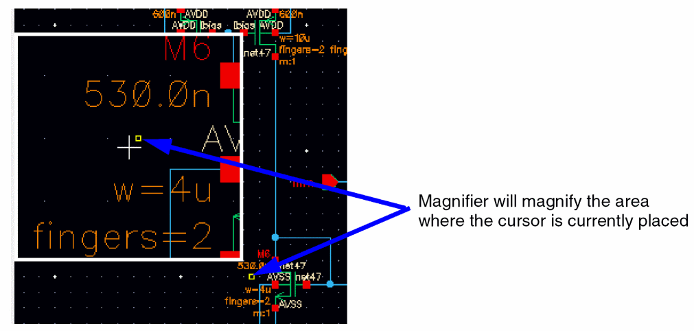
To switch design canvas magnification off, again choose View – Magnifier to uncheck the feature.
Magnifier Bindkeys
The following bindkeys can be used inconjunction with the magnifier:
For more details, see hiSetBindKey.
Customizing Magnifier Settings
-
To customize the use of the magnifier select Options – Magnifier.
This will display the Magnifier Options form, which will be synchronized to reflect the magnifier settings currently displayed in the window.
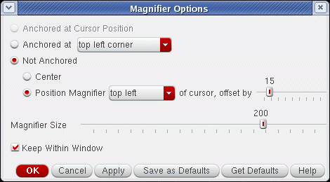
Figure 1-11 The Magnifier Options Form
Redrawing a Window
Viewing the Same Cell in Two Windows
Use the Copy Window command to see the same cellview from different zoom and pan settings simultaneously. This feature lets you work in one area of the cellview and still have a reference window showing the entire cellview.
To view the same cellview in two windows,
-
Choose Window – Copy Window.
A copy of the current cellview opens in a new window.
The copy has the same title as the original. Any change you make in either window affects both windows.
Cycling Between Windows and Views
You can cycle between the last ten window zoom or pan views that are in memory using either:
For more information on retrieving previously created views see
For more information on moving through a design hierarchy see
Saving View Area Settings in Memory
You can temporarily store your current viewing area. This procedure is useful when you want to look at one section of the design, move to a new section, and then return to the first section.
To temporarily save your viewing area,
-
Choose View – Save/Restore – Save View.
The Save View form appears. - In the Name field, type the name you want to assign to your current view.
- Click OK.
Restoring View Area Settings
To restore a saved viewing area,
-
Choose View – Save/Restore – Restore View.
The Restore View form appears, listing the names you assigned with the View – Save/Restore – Save View command. - Click once on the name.
-
Click OK.
The previously saved viewing area appears.
Click-Lock
This functionality allows you to switch between the LMB and RMB operation. You can perform various RMB commands and switch back to the LMB commands, such as zooming the selected area on the canvas. When click-lock is enabled, you do not need to hold the left mouse button anymore to keep the drag command active for the selection box. Instead, you can release the left mouse button and complete the command.
This functionality is useful for commands that involve left mouse drag, such as drawing a rectangle shape. To set the opposite corner of the selected box or rectangle, click the left mouse button again.
Refer to the following steps for creating a selection box using click-lock.
- Click the left mouse button and drag to create a rectangle.
- Right-click while holding the left mouse button.
-
Release the left mouse button. Lock has been activated now, as shown below.
- Perform the required RMB action on the canvas.
Showing and Hiding Labels and Notes
You can use a number of options in the View menu to determine (toggle on and off) what note and label information is to be shown on the design canvas.
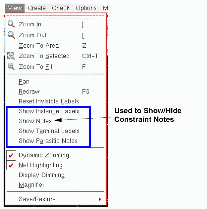
Figure 1-13 Show/Hide Labels and Notes
The Component Browser
You can use the Component Browser to view and select the contents of the libraries you specify in your cds.lib file. As an alternative, you can use the Library Browser.
The following sections provide information about the Component Browser.
- Accessing and Using the Component Browser
- Changing the Browser Type Option to the Component Browser
- Opening the Component Browser
- Opening the Add Instance Form Instead of the Component Browser
- Listing Components from Several Libraries
- Changing the Component Browser Display
Accessing and Using the Component Browser
You can use the Component Browser:
-
To view the contents of the libraries specified in your
cds.libfile - To select the components you want to add to your design
Changing the Browser Type Option to the Component Browser
To access the Component Browser,
-
Choose Options – Editor to display the Editor Options form.
- In the Add Instance Browser Type option, select component.
- Click OK.
Opening the Component Browser
To open the Component Browser to add component instances from a library,
-
Choose Create – Instance.
The Component Browser form appears.
The form shows the top-level categories for the US_8ths library.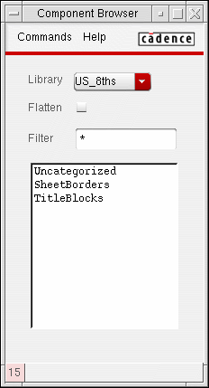
Opening the Add Instance Form Instead of the Component Browser
If you have specified the Component Browser as the default browser but want to open the Add Instance form first when you choose Create – Instance,
-
From the Component Browser, choose Commands – Preferences.
The Component Browser Preferences form appears.
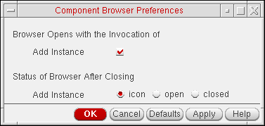
- Turn off the Browser Opens with the Invocation of Add Instance option.
- Click OK.
Listing Components from Several Libraries
To list components from several libraries,
-
From the Component Browser, choose Commands – Add Library.
The Component Browser form expands to display the contents of another library.
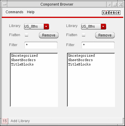
- From the Library cyclic fields, choose the libraries that you want to browse.
Changing the Component Browser Display
To display all components within categories of a library,
-
Choose the Flatten option.
By default, Flatten is deselected, so the Component Browser displays a hierarchical list of components grouped by categories.
To limit the display to specific components,
-
Type a selection pattern in the Filter field.
By default, the Filter field contains an asterisk, so the Component Browser displays all library components.
The following table describes filter patterns.
Return to top